Service Manual HS60.pdf - 第275页
HS -60 Se rvic e Ma nual 7 DLM2 Co l lect&Plac e Head 03/2 003 US Issue 7.6 Dis mantli ng / fit tin g the fr on t part of the co lle ct&p lace he ad 273 Æ Ins ert the dist rib utor bl ock into the back part. 7 Æ …
7 DLM2 Collect&Place Head HS-60 Service Manual
7.6 Dismantling / fitting the front part of the collect&place head 03/2003 US Issue
272
7.6.3 Fitting the front part of the collect&place head
7
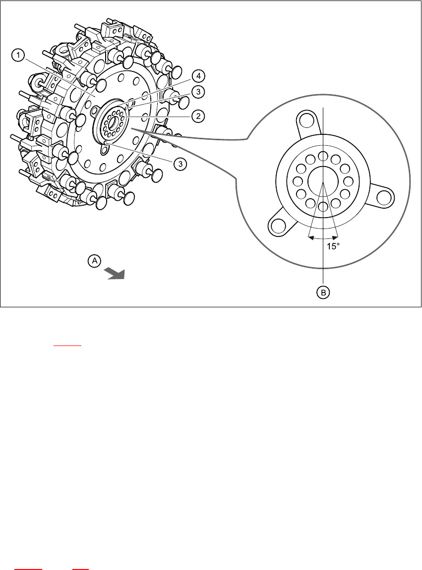
Fig. 7.6 - 3 Installation position of the distributor plate
Key to Fig. 7.6 - 3
(1) Star
(2) Distributor plate
(3) Parallel pins
(4) Raised part of the distributor plate
7
(A) Arrow points towards the back part
(B) Vertical sleeve position
7
Æ Grease the O-rings with Unisilikon.
Æ Push the small O-ring onto the tube.
Æ Place the large O-ring in the hole for the distributor block (item 7 in Fig.
7.2 - 1
, page 250).
Æ Check that the O-rings are seated correctly.
HS-60 Service Manual 7 DLM2 Collect&Place Head
03/2003 US Issue 7.6 Dismantling / fitting the front part of the collect&place head
273
Æ Insert the distributor block into the back part.
7
Æ Check that the distributor plate is inserted correctly:
– The circular raised part (4) of the distributor plate (2) points towards (A) the back part of the
collect&place head.
– The parallel pins (3) on the star engage in the holes in the distributor plate.
Æ Turn the star approximately 15° away from the vertical sleeve position (B).
Æ Place the front part on the back part so that the parallel pins are aligned with the holes in the
front part.
Æ Carefully the push front part against the back part until it lies flat against the back part.
Æ Attach the M4x16 four hexagon socket-head screws, see item A in Figs. 7.6 - 1 and 7.6 - 2.
Æ Restore the electrical connections (see Fig. 7.6 - 1).
Æ Connect the compressed air hose.
PLEASE NOTE: 7
Make sure that the folded part of the ribbon cable for the "Z-axis up" light barrier is pushed
back under the illumination board. 7
7.6.4 Settings
Æ Start the placement system.
Æ Use the SITEST program to calibrate the component camera.
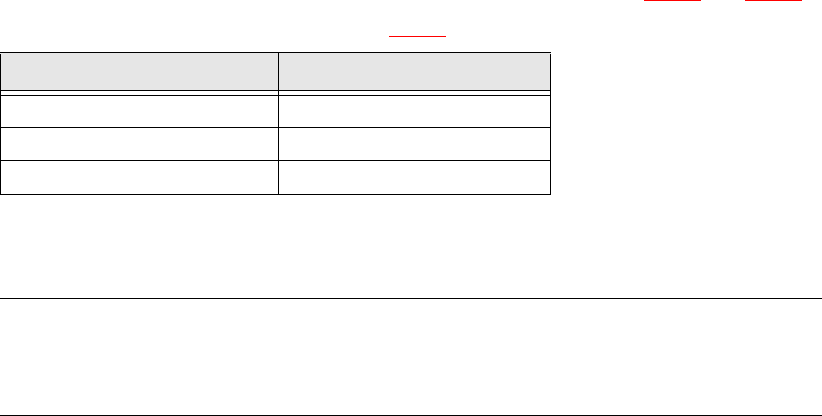
Cable Head board
00333491-W1 X14
00333491-W2 X13
00341220 X9
Tab. 7.6 - 1 Plug-in connections between front of collect&place head and head board

7 DLM2 Collect&Place Head HS-60 Service Manual
7.7 Replacing the 24x24 component camera (00336791-02) 03/2003 US Issue
274
7.7 Replacing the 24x24 component camera
(00336791-02)
7.7.1 Tools and equipment
– Set of DIN 911 Allen keys
– SITEST program
7.7.2 Parts
24x24 component camera, item no. 00335990-02 7
PLEASE NOTE:
The component camera is replaced as a complete unit consisting of the lens system, camera, am-
plifier, illumination planes and "Illumination controller" board. 7
7.7.3 Dismantling the component camera
Æ Dismantle the front part of the collect&place head as described in Section 7.6, page 269 on-
ward.
Æ Remove the ribbon cable plug from socket X3 on the "component illumination control" board
(see Fig. 7.5 - 1
).
Æ Undo the four M4x 10 hexagon socket-head screws for fixing the component camera.
Æ Carefully detach the component camera.
7.7.4 Fitting the component camera
Æ Make sure that all contact surfaces are clean.
Æ Place the holes in the camera on the parallel pins (see item 7 in Fig. 7.7 - 1).