Service Manual HS60.pdf - 第276页
7 DL M2 Co llec t &P lace Head H S-6 0 S erv ic e Manu al 7. 7 R ep laci ng th e 2 4 x2 4 co mp on ent ca me ra (003 36 79 1-0 2) 03/ 2 003 U S I ssue 274 7.7 Replac ing the 24x24 compone nt camera (003367 91-02) 7.7…
HS-60 Service Manual 7 DLM2 Collect&Place Head
03/2003 US Issue 7.6 Dismantling / fitting the front part of the collect&place head
273
Æ Insert the distributor block into the back part.
7
Æ Check that the distributor plate is inserted correctly:
– The circular raised part (4) of the distributor plate (2) points towards (A) the back part of the
collect&place head.
– The parallel pins (3) on the star engage in the holes in the distributor plate.
Æ Turn the star approximately 15° away from the vertical sleeve position (B).
Æ Place the front part on the back part so that the parallel pins are aligned with the holes in the
front part.
Æ Carefully the push front part against the back part until it lies flat against the back part.
Æ Attach the M4x16 four hexagon socket-head screws, see item A in Figs. 7.6 - 1 and 7.6 - 2.
Æ Restore the electrical connections (see Fig. 7.6 - 1).
Æ Connect the compressed air hose.
PLEASE NOTE: 7
Make sure that the folded part of the ribbon cable for the "Z-axis up" light barrier is pushed
back under the illumination board. 7
7.6.4 Settings
Æ Start the placement system.
Æ Use the SITEST program to calibrate the component camera.
Cable Head board
00333491-W1 X14
00333491-W2 X13
00341220 X9
Tab. 7.6 - 1 Plug-in connections between front of collect&place head and head board

7 DLM2 Collect&Place Head HS-60 Service Manual
7.7 Replacing the 24x24 component camera (00336791-02) 03/2003 US Issue
274
7.7 Replacing the 24x24 component camera
(00336791-02)
7.7.1 Tools and equipment
– Set of DIN 911 Allen keys
– SITEST program
7.7.2 Parts
24x24 component camera, item no. 00335990-02 7
PLEASE NOTE:
The component camera is replaced as a complete unit consisting of the lens system, camera, am-
plifier, illumination planes and "Illumination controller" board. 7
7.7.3 Dismantling the component camera
Æ Dismantle the front part of the collect&place head as described in Section 7.6, page 269 on-
ward.
Æ Remove the ribbon cable plug from socket X3 on the "component illumination control" board
(see Fig. 7.5 - 1
).
Æ Undo the four M4x 10 hexagon socket-head screws for fixing the component camera.
Æ Carefully detach the component camera.
7.7.4 Fitting the component camera
Æ Make sure that all contact surfaces are clean.
Æ Place the holes in the camera on the parallel pins (see item 7 in Fig. 7.7 - 1).
HS-60 Service Manual 7 DLM2 Collect&Place Head
03/2003 US Issue 7.7 Replacing the 24x24 component camera (00336791-02)
275
7
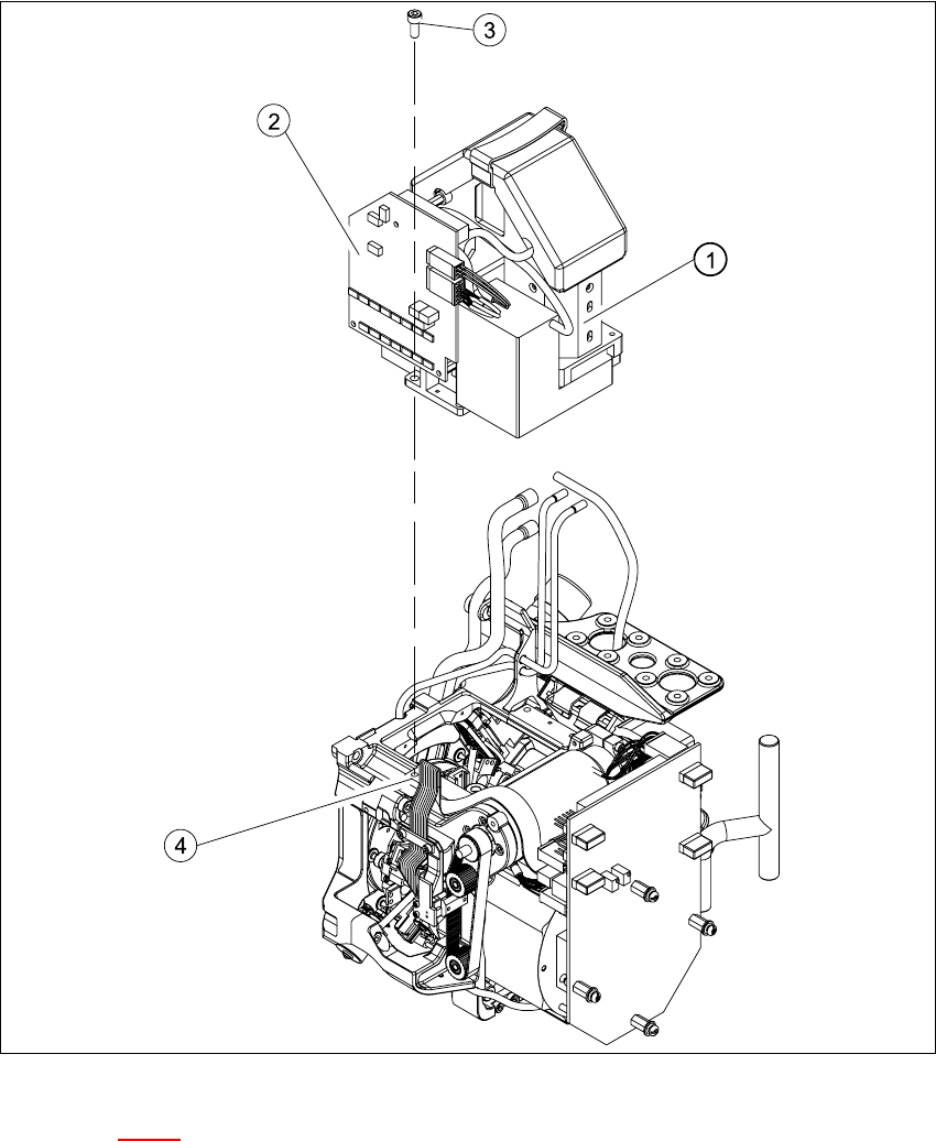
Fig. 7.7 - 1 Replacing the component camera
Key to Fig. 7.7 - 1
(1) 24x24 component camera
(2) "Component illumination controller" board
(3) 4 x M4x10 hexagon-socket head screws
(4) 2 parallel pins
7