Service Manual HS60.pdf - 第277页
HS -60 Se rvic e Ma nual 7 DLM2 Co l lect&Plac e Head 03/ 2003 US Is sue 7. 7 Repla cing the 24 x24 co mpo nent camer a (003 3679 1-02) 275 7 F ig . 7 .7 - 1 R ep la ci ng th e co mp on en t ca me ra Ke y to Fi g. 7.…

7 DLM2 Collect&Place Head HS-60 Service Manual
7.7 Replacing the 24x24 component camera (00336791-02) 03/2003 US Issue
274
7.7 Replacing the 24x24 component camera
(00336791-02)
7.7.1 Tools and equipment
– Set of DIN 911 Allen keys
– SITEST program
7.7.2 Parts
24x24 component camera, item no. 00335990-02 7
PLEASE NOTE:
The component camera is replaced as a complete unit consisting of the lens system, camera, am-
plifier, illumination planes and "Illumination controller" board. 7
7.7.3 Dismantling the component camera
Æ Dismantle the front part of the collect&place head as described in Section 7.6, page 269 on-
ward.
Æ Remove the ribbon cable plug from socket X3 on the "component illumination control" board
(see Fig. 7.5 - 1
).
Æ Undo the four M4x 10 hexagon socket-head screws for fixing the component camera.
Æ Carefully detach the component camera.
7.7.4 Fitting the component camera
Æ Make sure that all contact surfaces are clean.
Æ Place the holes in the camera on the parallel pins (see item 7 in Fig. 7.7 - 1).
HS-60 Service Manual 7 DLM2 Collect&Place Head
03/2003 US Issue 7.7 Replacing the 24x24 component camera (00336791-02)
275
7
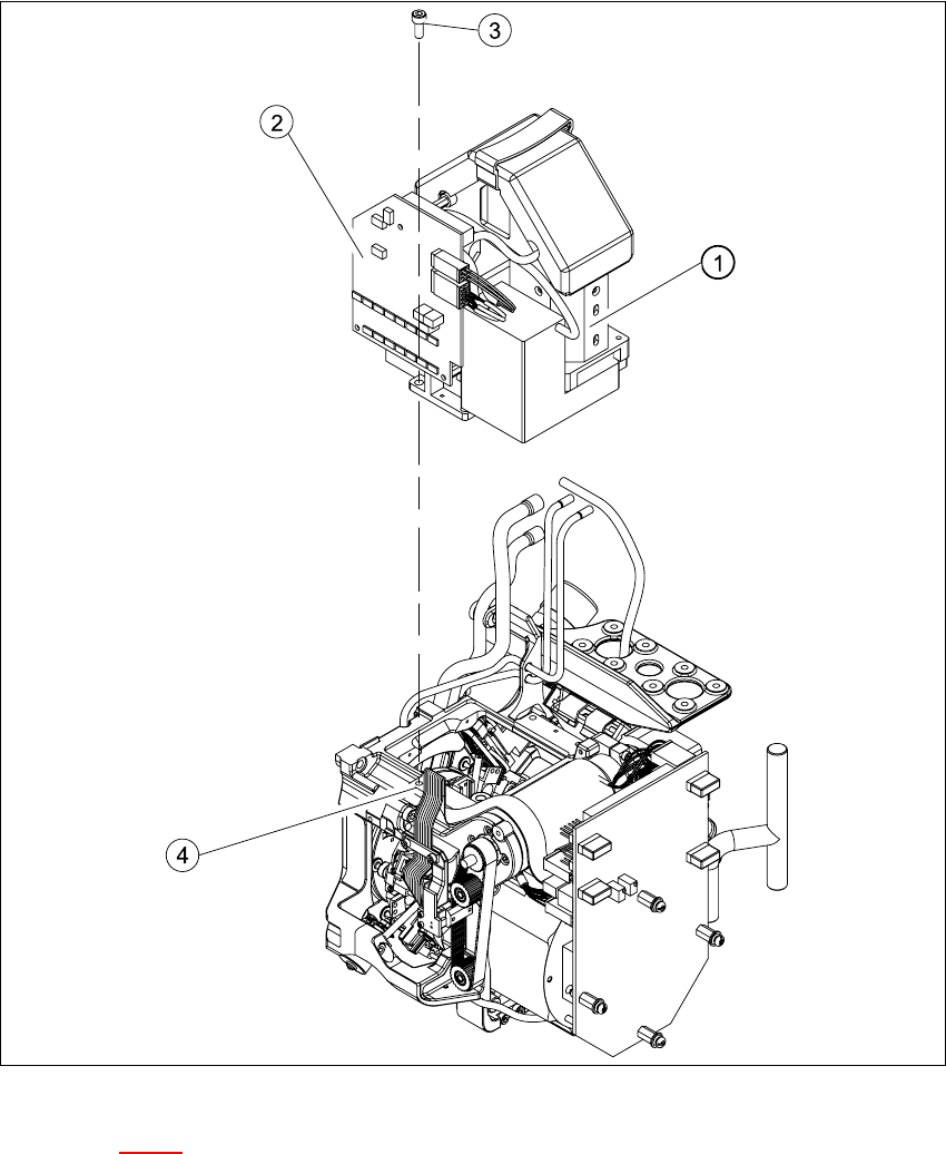
Fig. 7.7 - 1 Replacing the component camera
Key to Fig. 7.7 - 1
(1) 24x24 component camera
(2) "Component illumination controller" board
(3) 4 x M4x10 hexagon-socket head screws
(4) 2 parallel pins
7

7 DLM2 Collect&Place Head HS-60 Service Manual
7.7 Replacing the 24x24 component camera (00336791-02) 03/2003 US Issue
276
Æ Carefully push the camera against the collect&place head until the camera plinth is lying flat
on the contact surfaces on the front part of the collect&place head.
Æ Use the four M4x10 hexagon socket-head screws to fix the camera in place (see item 6 in Fig.
7.7 - 1
).
Æ Connect the ribbon cable to socket X3 on the "component illumination" board (see Fig. 7.5 - 1).
Æ Fit the front part of the collect&place head as described in Section 7.6.3, page 272.
Æ Fix the head cover in place.
7.7.5 Settings
Æ Start the placement system.
Æ Use the SITEST program to calibrate the collect&place head.