Service Manual HS60.pdf - 第279页
HS -60 Se rvic e Ma nual 7 DLM2 Co l lect&Plac e Head 03/ 2003 US Is sue 7.8 R epl acing the t urn ing stat ion ( 003 41780- 03) 277 7.8 Repla cing the tu rning s t ation (00 341780 -03) 7.8. 1 T ools and eq uipm ent…

7 DLM2 Collect&Place Head HS-60 Service Manual
7.7 Replacing the 24x24 component camera (00336791-02) 03/2003 US Issue
276
Æ Carefully push the camera against the collect&place head until the camera plinth is lying flat
on the contact surfaces on the front part of the collect&place head.
Æ Use the four M4x10 hexagon socket-head screws to fix the camera in place (see item 6 in Fig.
7.7 - 1
).
Æ Connect the ribbon cable to socket X3 on the "component illumination" board (see Fig. 7.5 - 1).
Æ Fit the front part of the collect&place head as described in Section 7.6.3, page 272.
Æ Fix the head cover in place.
7.7.5 Settings
Æ Start the placement system.
Æ Use the SITEST program to calibrate the collect&place head.

HS-60 Service Manual 7 DLM2 Collect&Place Head
03/2003 US Issue 7.8 Replacing the turning station (00341780-03)
277
7.8 Replacing the turning station (00341780-03)
7.8.1 Tools and equipment
– Set of DIN 911 Allen keys
– SITEST program
7.8.2 Parts
Turning station / DLM2, item no. 00341780-03 7
7.8.3 Dismantling the turning station
Æ Switch the placement system off and secure it to prevent switching on again as described in
Section 7.4
, page 261.
Æ Remove the plugs from sockets X12 and X18 on the head board.
7 DLM2 Collect&Place Head HS-60 Service Manual
7.8 Replacing the turning station (00341780-03) 03/2003 US Issue
278
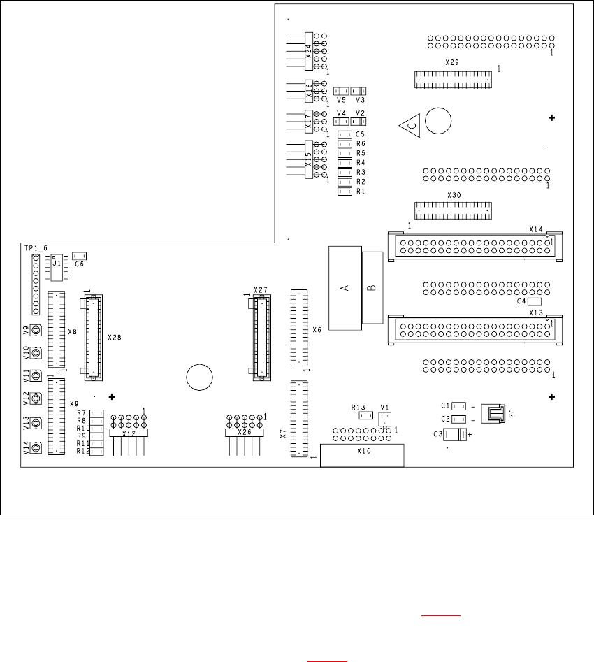
Fig. 7.8 - 1 Plug-in connections of the turning station on the head board
Æ Push the collect&place head until it reaches the stopper on the deflection roller of the X-axis
toothed belt.
Æ Undo the M3x25 hexagon socket-head screw (see item 2 in Fig. 7.8 - 2) on the rear panel of
the back part.
Æ Carefully pull the turning station (item 1 in Fig. 7.8 - 2) back and remove.