Service Manual HS60.pdf - 第282页
7 DL M2 Co llec t &P lace Head H S-6 0 S erv ic e Manu al 7. 8 R ep laci ng th e t ur n in g st at i on ( 0 0341 78 0-0 3) 03/2 00 3 US I ss ue 280 Æ P lug the cable into soc kets X1 2 an d X18 on the he ad board (se…
HS-60 Service Manual 7 DLM2 Collect&Place Head
03/2003 US Issue 7.8 Replacing the turning station (00341780-03)
279
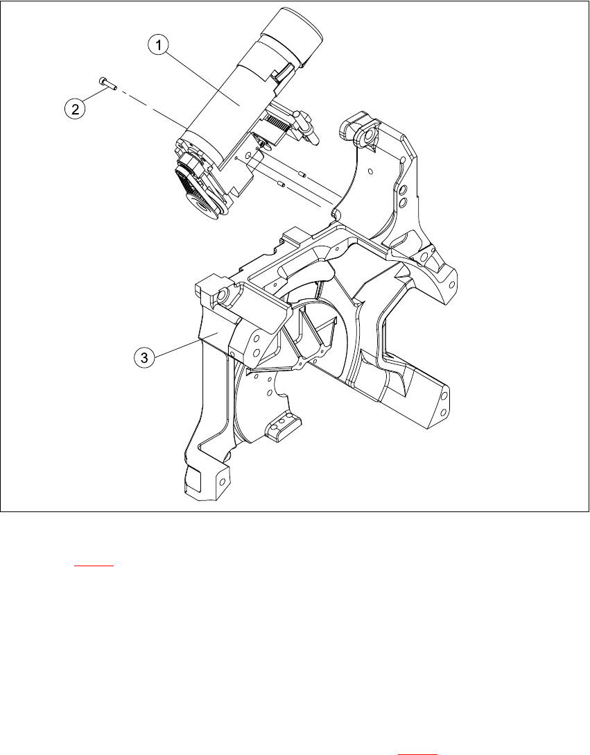
Fig. 7.8 - 2 Turning station / DLM2
Key to Fig. 7.8 - 2
(1) Turning station / DLM2
(2) M3x25 hexagon socket-head screw
(3) Back part of the collect&place head
7.8.4 Fitting the turning station
Æ Make sure that the contact surfaces of the turning station and rear panel are clean.
Æ Insert the M3 x 25 hexagon socket-head screw (item 2 in Fig. 7.8 - 1) into the hole in the cen-
tering station.
Æ Run the cable between the vacuum hose and the vacuum generation socket.
Æ Place the holes in the turning station on the parallel pins.
Æ Carefully push the turning station towards the back part until it reaches the stop.
Æ Fix the turning station with the hexagon socket-head screw.

7 DLM2 Collect&Place Head HS-60 Service Manual
7.8 Replacing the turning station (00341780-03) 03/2003 US Issue
280
Æ Plug the cable into sockets X12 and X18 on the head board (see item X12 and X18 in Fig.
7.8 - 1
, page 278.
7.8.5 Settings
Æ Switch the placement system on and start it up.
Æ Use the SITEST program to run a function test.

HS-60 Service Manual 7 DLM2 Collect&Place Head
03/2003 US Issue 7.9 Replacing the valve positioning drive for the placement (00368075-01) and reject circuits (00367768-01)
281
7.9 Replacing the valve positioning drive for the placement
(00368075-01) and reject circuits (00367768-01)
7.9.1 Tools and equipment
– Set of DIN 911 Allen keys
– Set of Phillips screwdrivers
– SITEST program
– Feeler gauge, item no. 00325445-01
7.9.2 Parts
Valve positioning drive, placement circuit, item no. 00368075-01 (Pos. 1 in Fig. 7.9 - 1)
Valve positioning drive, reject circuit, item no. 00367768-01 (Pos. 2 in Fig. 7.9 - 1
) 7
7.9.3 Dismantling the valve positioning drive
Æ Remove the collect&place head from the head mount (see Section 7.5.3, page 263).
Æ Undo the two M2x6 Phillips screws on the ribbon cable clamp (items 3 and 4 in Fig. 7.9 - 1).
Æ Undo the M3x10 hexagon socket-head screw (item 4 in Fig. 7.9 - 1).
Æ Carefully remove the valve positioning drive (item 1 or 2 in Fig. 7.9 - 1).