Service Manual HS60.pdf - 第283页
HS -60 Se rvic e Ma nual 7 DLM2 Co l lect&Plac e Head 03/ 2003 US Issu e 7.9 Repl acin g the val ve pos i ti onin g drive for th e plac ement ( 0036 8075-0 1) and r eje ct circ uits (0 0367 768-0 1) 281 7.9 Replacing…

7 DLM2 Collect&Place Head HS-60 Service Manual
7.8 Replacing the turning station (00341780-03) 03/2003 US Issue
280
Æ Plug the cable into sockets X12 and X18 on the head board (see item X12 and X18 in Fig.
7.8 - 1
, page 278.
7.8.5 Settings
Æ Switch the placement system on and start it up.
Æ Use the SITEST program to run a function test.

HS-60 Service Manual 7 DLM2 Collect&Place Head
03/2003 US Issue 7.9 Replacing the valve positioning drive for the placement (00368075-01) and reject circuits (00367768-01)
281
7.9 Replacing the valve positioning drive for the placement
(00368075-01) and reject circuits (00367768-01)
7.9.1 Tools and equipment
– Set of DIN 911 Allen keys
– Set of Phillips screwdrivers
– SITEST program
– Feeler gauge, item no. 00325445-01
7.9.2 Parts
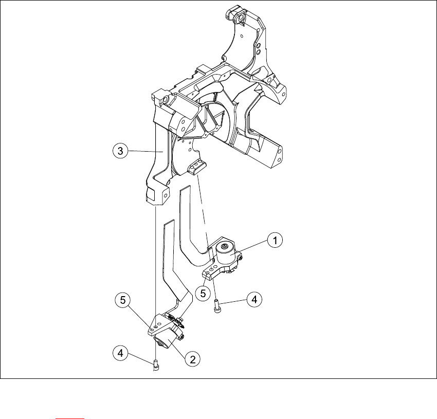
Valve positioning drive, placement circuit, item no. 00368075-01 (Pos. 1 in Fig. 7.9 - 1)
Valve positioning drive, reject circuit, item no. 00367768-01 (Pos. 2 in Fig. 7.9 - 1
) 7
7.9.3 Dismantling the valve positioning drive
Æ Remove the collect&place head from the head mount (see Section 7.5.3, page 263).
Æ Undo the two M2x6 Phillips screws on the ribbon cable clamp (items 3 and 4 in Fig. 7.9 - 1).
Æ Undo the M3x10 hexagon socket-head screw (item 4 in Fig. 7.9 - 1).
Æ Carefully remove the valve positioning drive (item 1 or 2 in Fig. 7.9 - 1).
7 DLM2 Collect&Place Head HS-60 Service Manual
7.9 Replacing the valve positioning drive for the placement (00368075-01) and reject circuits (00367768-01) 03/2003 US Issue
282
7
Fig. 7.9 - 1 Replacing the valve positioning drive
Key to Fig. 7.9 - 1
(1) "Placement circuit" valve positioning drive
(2) "Reject circuit" valve positioning drive
(3) Back part of the collect&place head
(4) M3x10 hexagon socket-head screw
(5) Parallel pins, 2 x per drive
7