Service Manual HS60.pdf - 第286页
7 DL M2 Co llec t &P lace Head H S-6 0 S erv ic e Manu al 7.9 R epl ac ing the valve posit ion ing dri ve for th e plac ement (0036 8075 -01) a nd re ject circ uits (00367 768-0 1) 03/20 0 3 US Is sue 284 7 F ig. 7. …
HS-60 Service Manual 7 DLM2 Collect&Place Head
03/2003 US Issue 7.9 Replacing the valve positioning drive for the placement (00368075-01) and reject circuits (00367768-01)
283
7.9.4 Fitting the valve positioning drive
Æ Insert the valve positioning drive, making sure that it is seated correctly on the parallel pins.
Æ Loosely tighten the hexagon socket-head screw.
Æ Use the cable clamp assemblies (items 2, 3, and 4 in Fig. 7.9 - 2) to fix the ribbon cables in
position, ensuring that the ribbon cables are not squashed.
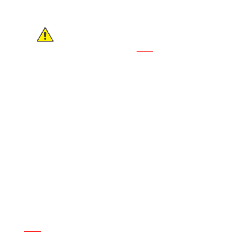
CAUTION 7
Check that the ribbon cables (item 1 and 2 in Fig. 7.9 - 2
) are laid correctly. The ribbon cable
(item 2 in Fig. 7.9 - 2
) from the valve adjustment unit to the reject station (item 6 in Fig. 7.9 -
2) must run outside the hole (item 5 in Fig. 7.9 - 2), otherwise it will be damaged when the
collect&place head is fitted on the head mount. 7
7
7
7
7
7
7
7
7
7
7
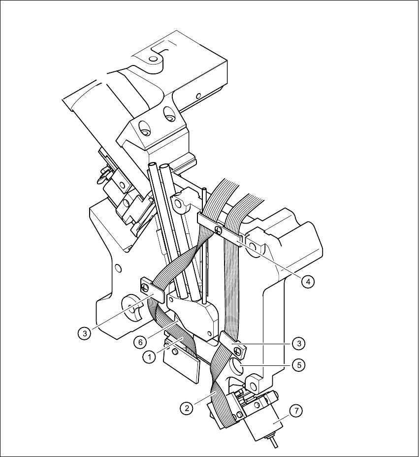
Key to Fig. 7.9 - 2
(1) Flat ribbon cable for the ’Placement’ valve adjustment unit
(2) Flat ribbon cable for the ’Reject circuit’ valve adjustment unit
(3) Cable clamp assembly
(4) Cable clamp assembly
(5) Hole
(6) ’Placement’ valve positioning drive
(7) ’Reject circuit’ valve positioning drive
7
7 DLM2 Collect&Place Head HS-60 Service Manual
7.9 Replacing the valve positioning drive for the placement (00368075-01) and reject circuits (00367768-01) 03/2003 US Issue
284
7
Fig. 7.9 - 2 Laying the ribbon cables for the valve adjustment drives
HS-60 Service Manual 7 DLM2 Collect&Place Head
03/2003 US Issue 7.9 Replacing the valve positioning drive for the placement (00368075-01) and reject circuits (00367768-01)
285
7.9.5 Mechanical adjustment
7
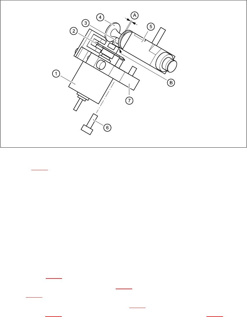
Fig. 7.9 - 3 Mechanical adjustment of the valve positioning drives
Key to Fig. 7.9 - 3
(1) Stepping motor
(2) Adjusting disk
(3) Deep-groove ball bearings
(4) Valve plunger
(5) Valve casing
(6) M3x10 hexagon socket-head screw
(7) Valve positioning drive (flange)
7
Æ Use the feeler gauge to set the distance between the valve plunger and valve casing to 0.2 mm
(item A in Fig. 7.9 - 3
).
Æ Turn the adjusting disk (see item 2 in Fig. 7.9 - 3) until the deep-groove ball bearings (item 3
in Fig. 7.9 - 3
) point towards the valve casing.
Æ Move the valve positioning drive (item 7 in Fig. 7.9 - 3) so that the deep-groove ball bearings
(item 3 in Fig. 7.9 - 3
) come into contact with the valve plunger (item 4 in Fig. 7.9 - 3) at
position B.
Æ Use the hexagon socket-head screw (item 6) to fix valve adjustment unit in this position.