Service Manual HS60.pdf - 第287页
HS -60 Se rvic e Ma nual 7 DLM2 Co l lect&Plac e Head 03/ 2003 US Issu e 7.9 Repl acin g the val ve pos i ti onin g drive for th e plac ement ( 0036 8075-0 1) and r eje ct circ uits (0 0367 768-0 1) 285 7.9. 5 Mechan…
7 DLM2 Collect&Place Head HS-60 Service Manual
7.9 Replacing the valve positioning drive for the placement (00368075-01) and reject circuits (00367768-01) 03/2003 US Issue
284
7
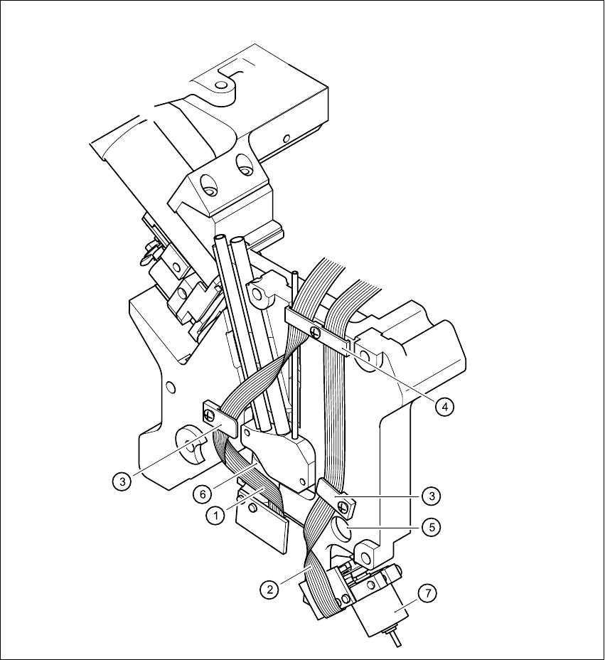
Fig. 7.9 - 2 Laying the ribbon cables for the valve adjustment drives
HS-60 Service Manual 7 DLM2 Collect&Place Head
03/2003 US Issue 7.9 Replacing the valve positioning drive for the placement (00368075-01) and reject circuits (00367768-01)
285
7.9.5 Mechanical adjustment
7
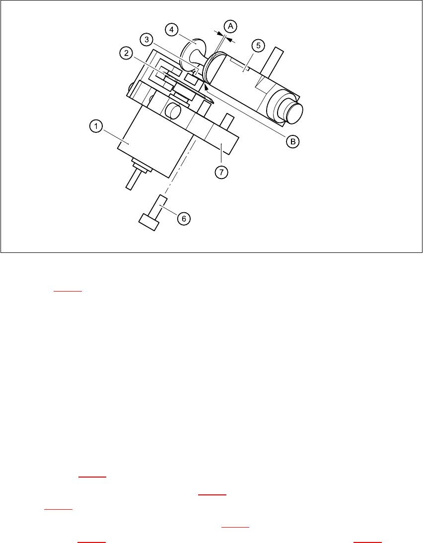
Fig. 7.9 - 3 Mechanical adjustment of the valve positioning drives
Key to Fig. 7.9 - 3
(1) Stepping motor
(2) Adjusting disk
(3) Deep-groove ball bearings
(4) Valve plunger
(5) Valve casing
(6) M3x10 hexagon socket-head screw
(7) Valve positioning drive (flange)
7
Æ Use the feeler gauge to set the distance between the valve plunger and valve casing to 0.2 mm
(item A in Fig. 7.9 - 3
).
Æ Turn the adjusting disk (see item 2 in Fig. 7.9 - 3) until the deep-groove ball bearings (item 3
in Fig. 7.9 - 3
) point towards the valve casing.
Æ Move the valve positioning drive (item 7 in Fig. 7.9 - 3) so that the deep-groove ball bearings
(item 3 in Fig. 7.9 - 3
) come into contact with the valve plunger (item 4 in Fig. 7.9 - 3) at
position B.
Æ Use the hexagon socket-head screw (item 6) to fix valve adjustment unit in this position.

7 DLM2 Collect&Place Head HS-60 Service Manual
7.9 Replacing the valve positioning drive for the placement (00368075-01) and reject circuits (00367768-01) 03/2003 US Issue
286
Æ Attach the collect&place head to the head mount (see Section 7.5.4, page 267).
7.9.6 Settings
Æ Use the SITEST program to test that the valve positioning drive is functioning correctly.
Æ Use the SITEST program to calibrate the collect&place head.