Service Manual HS60.pdf - 第294页
7 DL M2 Co llec t &P lace Head H S-6 0 S erv ic e Manu al 7. 11 R e pl acin g l ig ht ba rr ie r ’ Z- a xi s up ’ ( 0 034 72 97 -01 ) 03/ 2 003 U S I ss ue 292 7.1 1.5 Setti ngs Æ No set tings are requi red .
HS-60 Service Manual 7 DLM2 Collect&Place Head
03/2003 US Issue 7.11 Replacing light barrier ’Z-axis up’ (00347297-01)
291
7
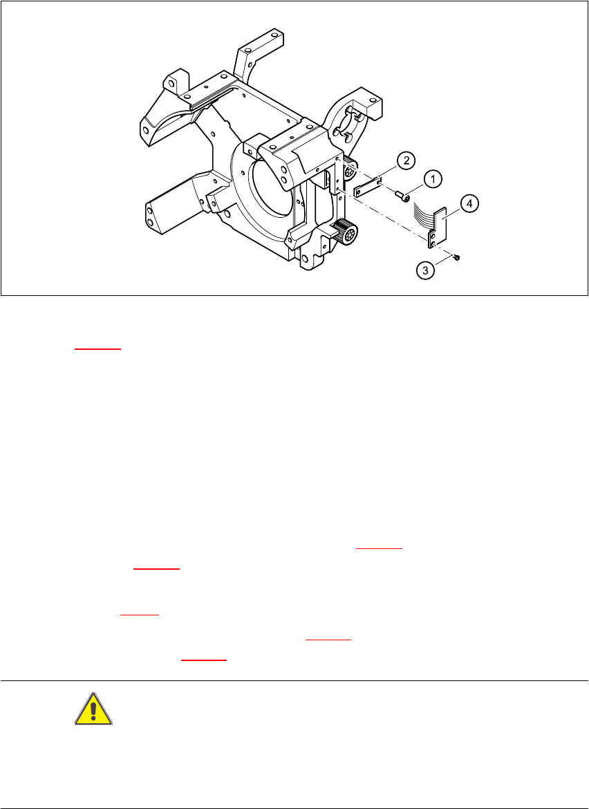
Fig. 7.11 - 1 Replacing the ’Z-axis up’ light barrier board
Key to Fig. 7.11 - 1
(1) 2 x M2.0x4 hexagon socket-head screw
(2) Cable clamp assembly, flat
(3) 2 Phillips screws (1.6x3)
(4) Light barrier board ’Z-axis up’
7.11.4 Fitting the ’Z-axis up’ light barrier
Æ Use the two M1.6x3 Phillips screws (see item 3 in Fig. 7.11 - 1) to fix the light barrier board
(see item 4 in Fig. 7.11 - 1
) in place.
Æ Connect the ribbon cable plug to socket X10 on the intermediate distribution board (see
item X10 in Fig. 7.2 - 5
).
Æ Use the ribbon cable clamp (see item 2 in Fig. 7.11 - 1) and the two hexagon socket-head
screws (see item 1 in Fig. 7.11 - 1
) to fix the ribbon cables.
CAUTION 7
Make sure that the ribbon cable is not squashed in the guide channel.
Make sure to push the folded part of the flat ribbon cable for the ’Z-axis up’ light barrier back under
the illumination board. 7
7 DLM2 Collect&Place Head HS-60 Service Manual
7.11 Replacing light barrier ’Z-axis up’ (00347297-01) 03/2003 US Issue
292
7.11.5 Settings
Æ No settings are required.

HS-60 Service Manual 7 DLM2 Collect&Place Head
03/2003 US Issue 7.12 Replacing the toothed belt of the Z-axis (00334936-01)
293
7.12 Replacing the toothed belt of the Z-axis (00334936-01)
7.12.1 Tools and equipment
– Set of DIN 911 Allen keys
– TSM belt tension measuring device, item no. 00326015-01
– "Measuring belt tensions" instructions
7.12.2 Parts
Toothed belt T2 / DLM2, item no. 00334936-01 7
7.12.3 Dismantling the toothed belt T2 / DLM2
Æ Switch the placement system off and secure it to prevent switching on again as described in
Section 7.4
, page 261.
Æ Undo the two M2.5x 8 hexagon socket-head screws (see item 1 in Fig. 7.12 - 1).
Æ Remove the stop (see item 2) and the tension jack (see item 4 in Fig. 7.12 - 1).
Æ Undo the two M2.5x 12 hexagon socket-head screws (see item 3 in Fig. 7.12 - 2) on the motor
clamp fitting 2 (see item 4 in Fig. 7.12 - 2
).
Æ Undo the two M3x14 hexagon socket-head screws (see item 6 in Fig. 7.12 - 2) on the motor
clamp fitting (see item 5 in Fig. 7.12 - 2
).
Æ Loosen the four hexagon socket-head screws M3x 5 (see item 1 in Fig. 7.12 - 2).
Æ Remove the toothed belt.
7