Service Manual HS60.pdf - 第304页
7 DL M2 Co llec t &P lace Head H S-6 0 S erv ic e Manu al 7. 14 R e plac in g t he fo rc ed ai r u ni t ( 003 67 79 3-0 1) 03/ 2 003 U S I ssue 302 Æ Detach the compresse d air h ose for the rej ect position (item 3 …
HS-60 Service Manual 7 DLM2 Collect&Place Head
03/2003 US Issue 7.14 Replacing the forced air unit (00367793-01)
301
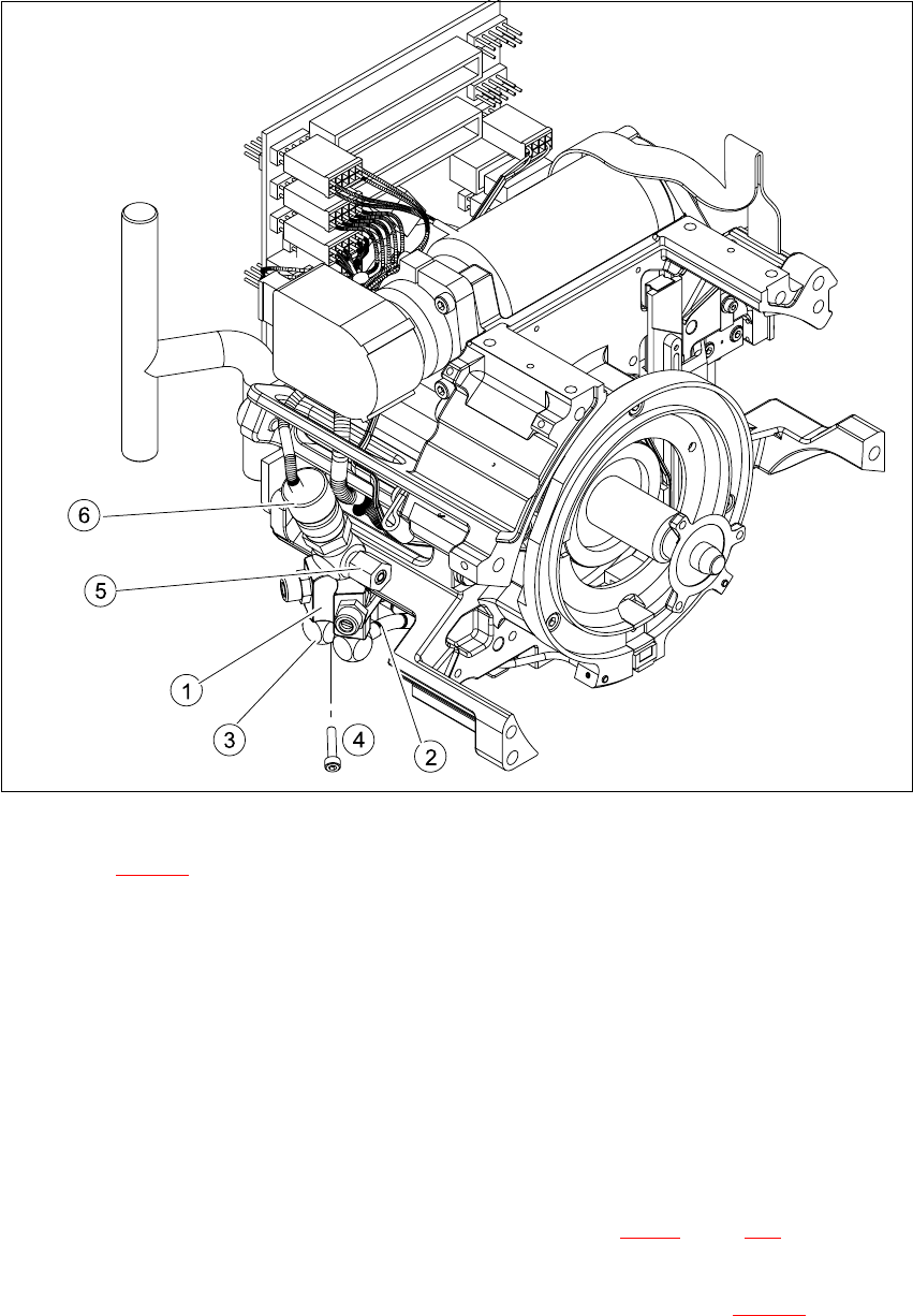
Fig. 7.14 - 1 Dismantling the forced air unit
Key to Fig. 7.14 - 1
(1) Forced air unit / DLM2
(2) To the "Placement circuit" compressed air tube and the compressed air sensor on the
intermediate distributor
(3) To the "Reject circuit" compressed air tube
(4) M3x20 hexagon socket-head screw
(5) SW8 union nut for the compressed air connection
(6) "Forced air" micro-relay valve
7
Æ Dismantle the intermediate distributor as described in Section 7.10.3, page 288.
Æ Detach the compressed air sensor.
Æ Detach the compressed air hose for the placement position (item 2 in Fig. 7.14 - 1) from the
"Placement circuit" compressed air tube.
7 DLM2 Collect&Place Head HS-60 Service Manual
7.14 Replacing the forced air unit (00367793-01) 03/2003 US Issue
302
Æ Detach the compressed air hose for the reject position (item 3 in Fig. 7.14 - 1) from the "Reject
circuit" compressed air tube.
Æ Undo the M3x20 hexagon socket head screw.
Æ Remove the forced air unit (item 1 in Fig. 7.14 - 1).
Æ Loosen the union nut (item 5 in Fig. 7.14 - 1) and detach the compressed air supply hose.
7.14.4 Fitting the forced air unit
Æ Connect the hoses.
Æ Use the hexagon socket-head screw to fix the forced air unit.
Æ Connect the plug to socket X6 on the intermediate distribution board (see Fig. 7.5 - 1.
CAUTION 7
Risk of injury from the compensating tube when the hose is pushed onto the measuring tube.7
Æ Fit the intermediate distributor.
7.14.5 Settings
Æ No settings are required.
HS-60 Service Manual 7 DLM2 Collect&Place Head
03/2003 US Issue 7.15 Replacing the silencer (00359582-01)
303
7.15 Replacing the silencer (00359582-01)
7.15.1 Parts
Silencer, item no. 00359582-01 7
7.15.2 Replacing the silencer
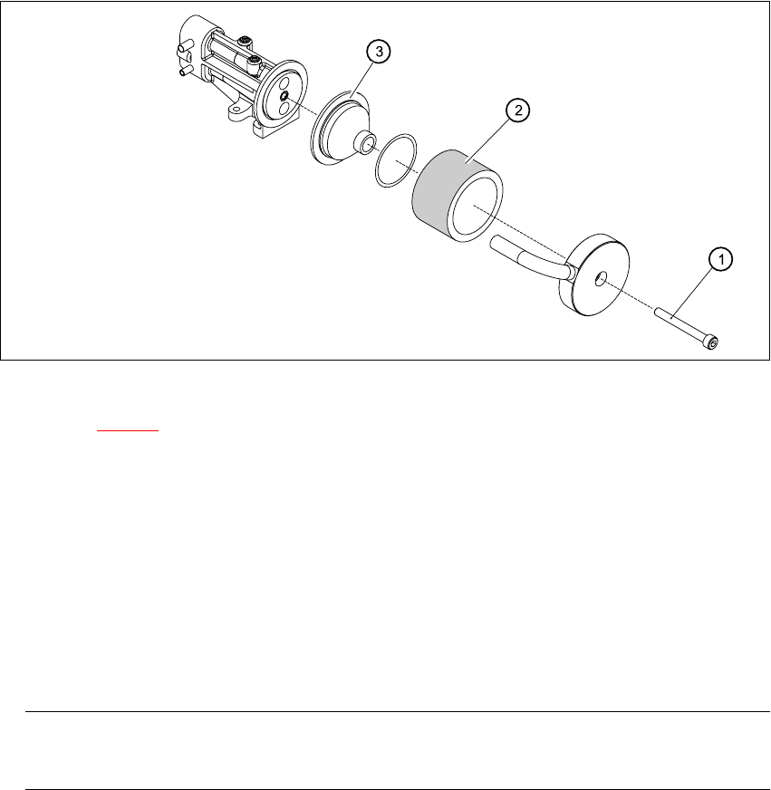
Fig. 7.15 - 1 Replacing the silencer
Key to Fig. 7.15 - 1
(1) Threaded rod
(2) Silencer
(3) Pre-silencer
7
Æ Turn the silencer (2) counter-clockwise to loosen.
Æ Pull out the threaded rod (1).
Æ Remove the pre-silencer (3) from the silencer.
PLEASE NOTE 7
Always wear gloves when handling new silencers. 7
Æ Insert the pre-silencer and the threaded rod.
Æ Turn the silencer clockwise to fix in position.