Service Manual HS60.pdf - 第307页
HS -60 Se rvic e Ma nual 7 DLM2 Co l lect&Plac e Head 03/ 2 003 U S Iss ue 7. 16 Re plac ing the sta r (003 4118 1-0 1) 305 F ig. 7. 16 - 1 R epla ci ng th e s tar Ke y to Fi g. 7.16 - 1 (1) Sleeve (2 ) Star , mo u n…

7 DLM2 Collect&Place Head HS-60 Service Manual
7.16 Replacing the star (00341181-01) 03/2003 US Issue
304
7.16 Replacing the star (00341181-01)
7.16.1 Tools and equipment
– Set of DIN 911 Allen keys
– Gauge for the star (collect&place head / DLM2), article number 00326164-01
– Power pack for the collect&place head / DLM2, article number 00353277-01
– Tray for transporting the collect&place head
– Laboratory gloves
7.16.2 Parts
Star, mounted / DLM2, article number 00341181-01 7
7.16.3 Dismantling the star
Æ Dismantle the front part of the collect&place head as described in Section 7.6, page 269 on-
wards.
Æ Place the front part of the collect&place head on the tray.
PLEASE NOTE:
Wear laboratory gloves when you remove the sleeves from the star. 7
Æ Remove all the sleeves (item 1 in Fig. 7.16 - 1) and place them in the sleeve box or on a soft,
clean surface.
Æ Undo the three M3x8 hexagon socket head screws (item 5 in Fig. 7.16 - 1).
Æ Raise the star slightly.
Æ Use a rotary movement to lift the star up and off.
HS-60 Service Manual 7 DLM2 Collect&Place Head
03/2003 US Issue 7.16 Replacing the star (00341181-01)
305
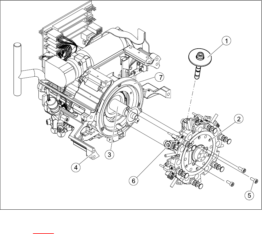
Fig. 7.16 - 1 Replacing the star
Key to Fig. 7.16 - 1
(1) Sleeve
(2) Star, mounted / DLM2
(3) Star drive
(4) Front part of collect&place head
(5) M3x8 hexagon socket head screws, 3x
(6) Segment
(7) Raceway

7 DLM2 Collect&Place Head HS-60 Service Manual
7.16 Replacing the star (00341181-01) 03/2003 US Issue
306
7.16.4 Fitting the star
PLEASE NOTE:
Remove any remaining sleeves before fitting the star.
Wear laboratory gloves when removing the sleeves. 7
Æ Push all the segments (item. 6 in Fig. 7.16 - 1) slightly outwards.
Æ Insert small Allen keys (e.g. size 2) into the holes for the star fixing screws (item 5 in Fig.
7.16 - 1
).
Æ Hold the star over the star drive shaft (item 3 in Fig. 7.16 - 1) so that the Allen keys slide into
the threaded holes in the star drive.
Æ Insert the star.
PLEASE NOTE:
Make sure that the vacuum hoses of the segments do not become squashed. 7
Æ Push all the segments inwards so that the segment ball bearings slide into the raceway (item
7 in Fig. 7.16 - 1
).
Æ Check that the star is seated flat on the drive shaft.
Æ Loosely tighten the three M3x8 hexagon socket head screws on the star so that the screws
can still move slightly in the fixing holes.
7.16.5 Adjusting the star with respect to the star's magnetic neutral position.
The aim of adjusting the star is to ensure that the vertical axis of segment no. 1 is aligned with the
magnetic neutral position of the star step motor. 7
Æ To do this, insert the gauge pin into the gauge for the star and into the hole in the segment
no. 1, until it reaches the stop.
Æ Pull off the motor line plug of the star motor from socket X5 on the intermediate distribution
board and connect the motor line to the power supply.
Æ Connect the power supply unit to main power.
Æ Tighten the three M3x8 hexagon socket head screws on the star.
Æ Remove the gauge pin.