Service Manual HS60.pdf - 第310页
7 DL M2 Co llec t &P lace Head H S-6 0 S erv ic e Manu al 7. 16 R e plac in g t he s tar (00 34 11 8 1-0 1) 03/ 2 003 U S I ssue 308 Fig . 7.1 6 - 2 Loose ning th e st ar dri ve Key t o Fi g. 7.1 6 - 2 (1) S tar dri …

HS-60 Service Manual 7 DLM2 Collect&Place Head
03/2003 US Issue 7.16 Replacing the star (00341181-01)
307
Æ Insert the gauge pin again into the gauge for the star and into the hole in the segment, until it
reaches the stop. Then check:
– that the gauge pin can be inserted easily.
– that the star does not rotate out of its current position as a result.
If both of these conditions are fulfilled, then the star has been fitted correctly. 7
Æ Disconnect the power pack from the power source.
Æ Continue from Section 7.6.3 "Fitting the front part of the collect&place head".
Æ Repeat the adjustment procedure if the gauge pin does not slide easily into the hole.
CAUTION
The maximum operating time of the power pack for the star motor is five minutes. Do NOT
exceed this time. If you have to disconnect the power pack from the power source because
it has been operating for five minutes, always insert the gauge pin before switching the power
pack on again. 7
If you still cannot fit the star in the magnetic neutral position of the star motor, follow the
instructions below: 7
Æ Loosen the four M5x16 hexagon socket head screws (item 2 in Fig. 7.16 - 2) for fixing the star
drive (item 1 in Fig. 7.16 - 2
) and turn the star drive in the direction that will allow the star to be
adjusted with respect to the magnetic neutral position. Tighten the four hexagon socket head
screws in this position.
7 DLM2 Collect&Place Head HS-60 Service Manual
7.16 Replacing the star (00341181-01) 03/2003 US Issue
308
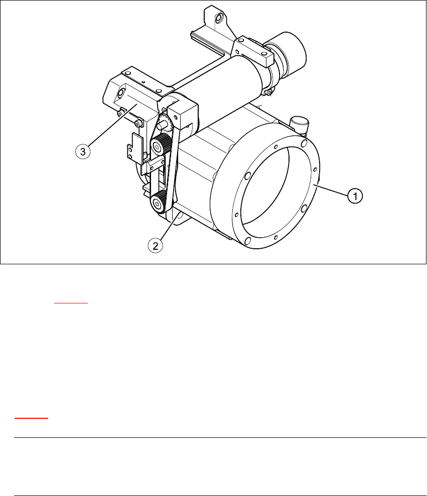
Fig. 7.16 - 2 Loosening the star drive
Key to Fig. 7.16 - 2
(1) Star drive, digital / DLM2
(2) M5x16 hexagon socket head screws, 4x
(3) Front part of collect&place head
7
Æ Loosen the three M3x8 hexagon socket head screws (item 5 in Fig.
7.16 - 1
) for fixing the star again and repeat the adjustment procedure.
PLEASE NOTE:
The star is fitted correctly until it no longer moves out of position when the gauge pin is
removed after disconnecting the star drive from the power supply. 7
HS-60 Service Manual 7 DLM2 Collect&Place Head
03/2003 US Issue 7.16 Replacing the star (00341181-01)
309
7.16.6 Fitting the front part of the collect&place head
Æ Remove the gauge for the star.
Æ Insert the power cable plug connector for the star drive into socket X5 on the intermediate ter-
minal block. The plug connector is an anti-rotation connector.
Æ Fit the front part of the collect&place head on the back part of the collect&place head (see Sec-
tion 7.6.3
, page 272).
Æ Adjusting the star with respect to the star's magnetic neutral position (see Section 7.16.5).
7.16.7 Use the SITEST program to determine the star zero point correction.
RISK OF HEAD CRASH
Always remove the gauge for the star, otherwise parts of the machine may be damaged when you
fit the front part of the collect&place head. 7
PLEASE NOTE:
Always remove all the sleeves from the star when you carry out the star zero point correction pro-
cedure. 7
Æ Load the SITEST program.
Æ Select "C&P Head" => "Head No." (HS-60) =>
"Axes" => "Star Axis" => "Positions" => "Zero Point Correction".
Æ Enter a "0" in the "Zero Point Correction" line and carry out the star axis reference run.
Æ Disable the star axis and turn the star clockwise until segment no. 1 is in the placement posi-
tion.
Æ Fit the "gauge for the star" on the front part of the collect&place head once more.
Æ Insert the gauge pin into the "gauge for the star" and into the hole in the segment no. 1, until it
reaches the stop.
Æ Select "Axes" => "Star Axis" => "Positions", and then exit the "Positions" menu option.
This will update the actual position display.
Æ Switch to "Positions" = > "Zero Point Correction", and enter the value for the updated actual
position (including the sign) on the "Zero Point Correction" line.
Æ Select "Accept".