Service Manual HS60.pdf - 第321页
HS -60 Se rvic e Ma nual 7 DLM2 Co l lect&Plac e Head 03/ 2 0 03 US Is sue 7. 19 Repl acin g the "Z-ax is dow n" se nsor (0 0321 524- 05) 319 7.19.4 Inst al ling the "Z -axis do wn" sen sor Æ T hr…
7 DLM2 Collect&Place Head HS-60 Service Manual
7.19 Replacing the "Z-axis down" sensor (00321524-05) 03/2003 US Issue
318
7
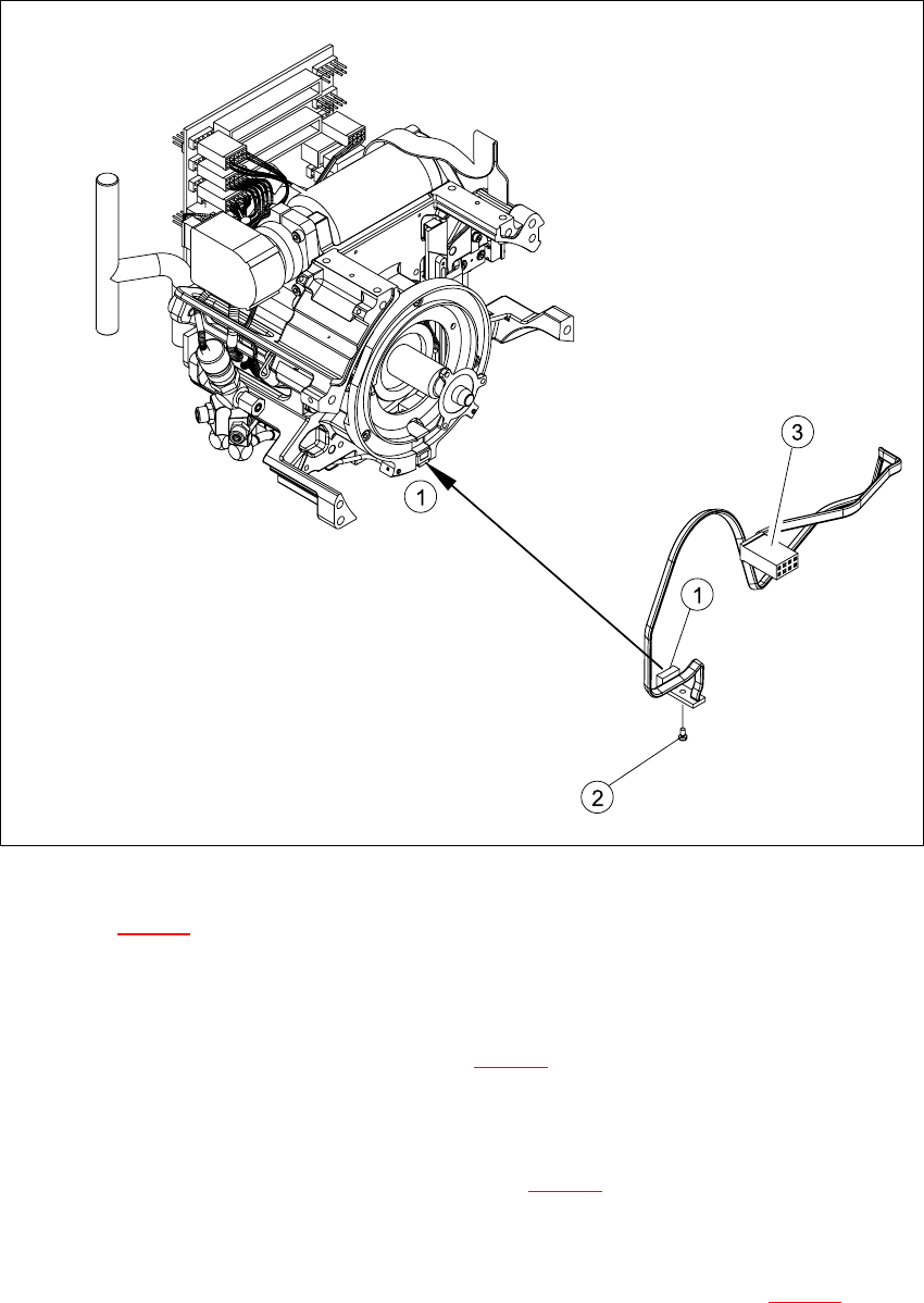
Fig. 7.19 - 1 Removing/installing the "z-axis down" sensor
Key to Fig. 7.19 - 1
(1) "Z-axis down" sensor
(2) Fixtures for sensor
(3) Plug for intermediate distribution board (see 7.10 - 2
)
7
Æ Push the z-axis down.
Æ Loosen the screw holding the sensor (item 2 in Fig. 7.19 - 1).
Æ Remove the cable clamps on the driver arm and star motor.
Æ Carefully pull the sensor and cable out of the front part of the collect&place head and remove
the plug (item 3) from socket X11 on the intermediate distribution board (see 7.10 - 2
).
HS-60 Service Manual 7 DLM2 Collect&Place Head
03/2003 US Issue 7.19 Replacing the "Z-axis down" sensor (00321524-05)
319
7.19.4 Installing the "Z-axis down" sensor
Æ Thread the sensor cable from the z-axis into the front part of the collect&place head.
Æ Fix the sensor (item 1 in Fig. 7.19 - 1) in position with the screw provided (item 2 in Fig. 7.19 -
1). Initially only screw loosely into the jaw of the z-axis.
Æ Fix the cable into place with the cable clamps.
Æ Check how the cable is run inside the front part of the collect&place head:
– If the z-axis has been pushed right out, the cable should lie loosely around the housing for
the star drive shaft. The cable must NOT be pulled tight.
– If the z-axis is pushed right in, the cable should run freely inside the front part of the col-
lect&place head, without touching the rotary encoder for the DP axis.
CAUTION
If the radius of the curvature is too small, the z-axis could jam or the light barrier cable may
break. 7
Once the cable is run in line with the required conditions, fix it in place with the angled clips
(item 3 and 4 in Fig. 7.19 - 1
). 7
Æ Insert the plug connector for the cable into socket X11 on the intermediate terminal block.
7.19.5 Adjusting the "Z-axis down" sensor
Æ Use the drill to set the distance between the white sleeve ring and the light barrier to 0.95 -1.25
mm.
Æ Fix the light barrier in place with the two screws.
7.19.6 Installing the star
Æ Fit and adjust the star, as described in Sections 7.16.4 and 7.16.5 from page 306 onwards.
Æ Install the front part of the collect&place head, as described in Section 7.6.3 from page 272
onwards.
7.19.7 Adjustments
Æ Use the SITEST program to check that the sensor is working correctly.

7 DLM2 Collect&Place Head HS-60 Service Manual
7.20 Replacing the complete Z-axis (03001959-01) 03/2003 US Issue
320
7.20 Replacing the complete Z-axis (03001959-01)
NOTE:
We recommend replacing the complete z-axis DLM2 after approx 100 million placements. 7
7.20.1 Tools and equipment
– Set of DIN 911 Allen keys
– Feeler gauge 0,2mm / 0,3mm
– Grease gun (article no. 03011577-01)
– Tray for transporting the collect&place head
– Laboratory gloves
7.20.2 Removal
7
Diagram 1 in Fig 7.20 - 1
Æ Dismantle the light barrier under the z-axis by loosening the two M1,6x3 DIN 84 screws.
Diagram 2 in Fig 7.20 - 1
Æ Carefully pull the cable out of the cable duct until it lies loosely.
Diagram 3 in Fig 7.20 - 1
Æ Loosen the connection between driver arm and driver bracket by removing the two M2x14 DIN
912 screws.
Diagram 4 in Fig 7.20 - 1
Æ Pull the driver arm, together with the centering pin, out of the driver bracket and move the driver
arm into stop position in the raceway.
Diagram 5 in Fig 7.20 - 1
Æ Remove the three screws holding the z-axis in place (2x M3x14, 1x M3x4).
7