Service Manual HS60.pdf - 第323页
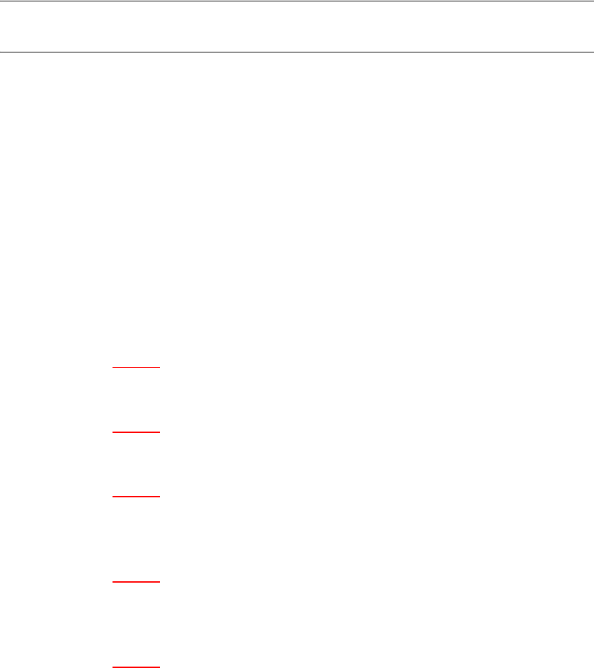
HS -60 Se rvic e Ma nual 7 DLM2 Co l lect&Plac e Head 03/ 2003 US Is sue 7.2 0 Rep laci ng th e com ple te Z-a xis (0 3001 959-0 1) 321 7 F ig. 7. 20 - 1 R em ovin g th e z -a xis
7 DLM2 Collect&Place Head HS-60 Service Manual
7.20 Replacing the complete Z-axis (03001959-01) 03/2003 US Issue
320
7.20 Replacing the complete Z-axis (03001959-01)
NOTE:
We recommend replacing the complete z-axis DLM2 after approx 100 million placements. 7
7.20.1 Tools and equipment
– Set of DIN 911 Allen keys
– Feeler gauge 0,2mm / 0,3mm
– Grease gun (article no. 03011577-01)
– Tray for transporting the collect&place head
– Laboratory gloves
7.20.2 Removal
7
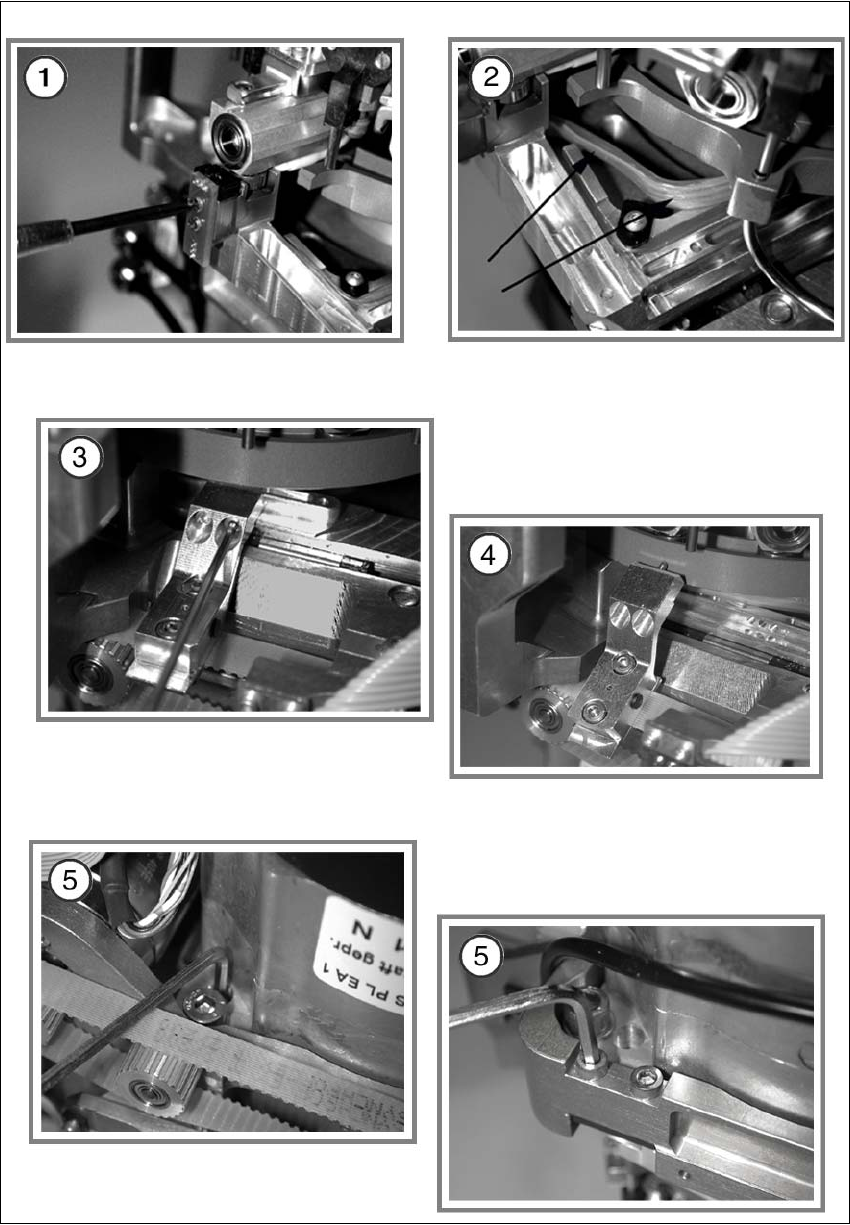
Diagram 1 in Fig 7.20 - 1
Æ Dismantle the light barrier under the z-axis by loosening the two M1,6x3 DIN 84 screws.
Diagram 2 in Fig 7.20 - 1
Æ Carefully pull the cable out of the cable duct until it lies loosely.
Diagram 3 in Fig 7.20 - 1
Æ Loosen the connection between driver arm and driver bracket by removing the two M2x14 DIN
912 screws.
Diagram 4 in Fig 7.20 - 1
Æ Pull the driver arm, together with the centering pin, out of the driver bracket and move the driver
arm into stop position in the raceway.
Diagram 5 in Fig 7.20 - 1
Æ Remove the three screws holding the z-axis in place (2x M3x14, 1x M3x4).
7
HS-60 Service Manual 7 DLM2 Collect&Place Head
03/2003 US Issue 7.20 Replacing the complete Z-axis (03001959-01)
321
7
Fig. 7.20 - 1 Removing the z-axis
7 DLM2 Collect&Place Head HS-60 Service Manual
7.20 Replacing the complete Z-axis (03001959-01) 03/2003 US Issue
322
7.20.3 Installation
Diagram 1 in Fig 7.20 - 2
Æ Rotate the star into the position shown and then pull the z-axis out of the guide by holding onto
its assembly plate.
Æ Clean the contact surface with SIPLACE cleansing tips and ethanol.
Diagram 2 in Fig 7.20 - 2
Æ Push the new z-axis guide into the groove provided.
Æ Press the reference edge (inner side) of the z-axis into the groove and fix the z-axis with the
screws provided.
Diagram 3 in Fig 7.20 - 2
Æ Use the feeler gauge to check the distance between the jaw and the groove of the raceway.
The permissible gap is between 0.2 and 0.3 mm.
Readjust the jaw if necessary.
Æ Reassemble the placement head in reverse order.
NOTE:
The board must be fitted centered to the jaws.
Make sure that the board does not rub against the frame (check with gauge if necessary). 7
Complete the following step at every second service interval for the head: 7
Diagram 4 in Fig 7.20 - 2
Æ Use the grease gun to apply a small amount of grease to the hole provided.
Make sure that too much grease doesn’t ooze out of the hole.
NOTE:
Where dirt is not excessive, the grease can be directly applied to the rail. 7