Service Manual HS60.pdf - 第326页
7 DL M2 Co llec t &P lace Head H S-6 0 S erv ic e Manu al 7. 20 R e plac in g t he c ompl et e Z - axis ( 030 0 19 59 -01 ) 03/ 200 3 US I ssue 324 7
HS-60 Service Manual 7 DLM2 Collect&Place Head
03/2003 US Issue 7.20 Replacing the complete Z-axis (03001959-01)
323
7
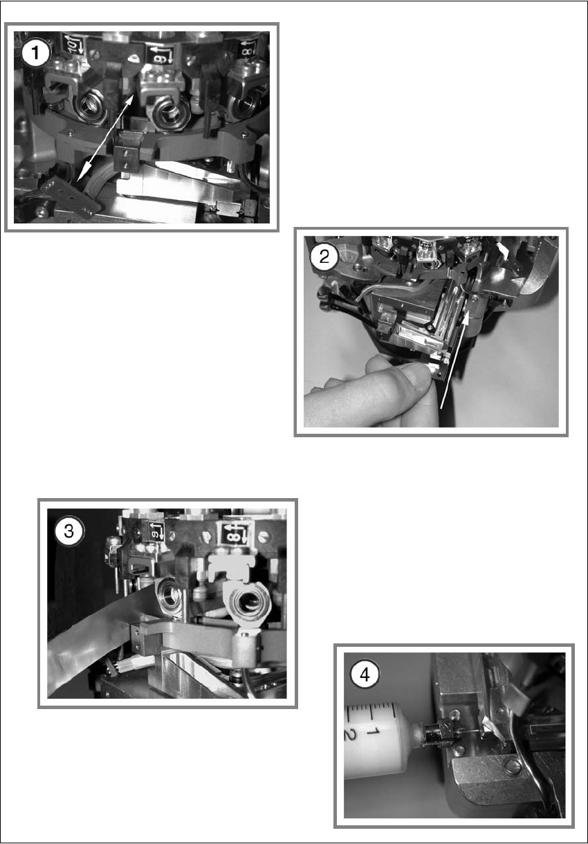
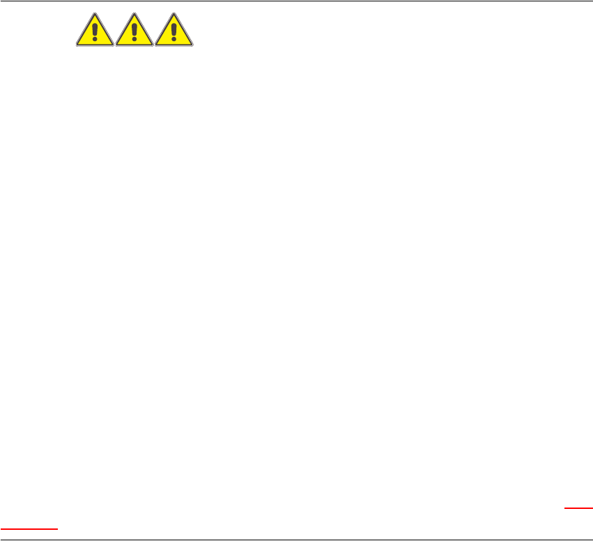
Fig. 7.20 - 2 Installing the z-axis
7 DLM2 Collect&Place Head HS-60 Service Manual
7.20 Replacing the complete Z-axis (03001959-01) 03/2003 US Issue
324
7
Service Manual HS-60 8 Movable Component Changeover Table
03/2003 US Issue 8.1 Safety Instructions
325
8 Movable Component Changeover
Table
8.1 Safety Instructions
DANGER
The chapters „Operational Safety“ and „Component Changeover Tables“ in the SIPLACE HS-60
user manual and the chapter „Operational Safety“ in this service manual take precedence.
These SIPLACE machines are powered by 120V / 208V +/- 5% (US version) or 3 x 230V/400V
+/-5% 50/ 60 Hz line voltage.
Parts of the system therefore carry dangerously high voltages! In specific modules the voltage is
present inside the machine base even when the main switch is turned off.
Handling the machines improperly or touching parts thereof which conduct high voltage may result
in death or serious physical injury as well as extensive property damage.
Observe the applicable accident prevention regulations, DIN standards and special safety codes
of your country at all times. DIN EN 60204 must be adhered to during all work inside the machine
base
The Siemens service engineer is the only person permitted to adjust / change the voltage, on the
basis of internal Siemens retrofitting instructions.
Furthermore, only the Siemens service engineer is permitted to adjust the height of the compo-
nent changeover table, on the basis of internal Siemens retrofitting instructions.
While working with the SITEST program, comply with the instructions in the DANGER text in Sec-
tion 8.5.7 „Final Steps“. 8