Service Manual HS60.pdf - 第334页
8 Mo v ab le Com pon en t C h ange o ve r Ta bl e Serv i ce M an ua l H S- 60 8. 5 R es ol ving pr obl ems 03/ 2 003 U S I ssue 332 8.5.2 Exchanging th e Bellows Cylin der DANGER In e xceptional cases, a faulty bel lows …

Service Manual HS-60 8 Movable Component Changeover Table
03/2003 US Issue 8.5 Resolving problems
331
8.5.1 Preparatory steps
Æ Move the component changeover table out of the machine, as described in the SIPLACE
HS-60 User Manual (hold the handle with both hands!)
If an empty, movable component changeover table is available, first proceed as follow
Æ Pull out the plug-and-socket connections of all of the feeder modules on the faulty compo-
nent changeover table.
Æ Place the feeder modules incl. the tape reel and knockout spindles (see Fig. 8.4.1 -> 2, 13,
14) in correct order on the new component table (in accordance with the specifications for
set-up optimization), insert the tapes and check the allocation of component / track (com-
ponent bar code scanner).
If there is an external set-up location available, carry out the setting up and inspection there
(see also Section 8.5.7
"Final Steps").
Æ Connect the new component changeover table to the machine, as described in the User
Manual.
Æ Resolve the problems with the dismantled component changeover table as indicated in the
relevant section below.
Æ If no other component changeover table is available,
continue as follows after resolving the problems as required:
– When exchanging the bellows cylinder:
Take the feeder modules from the changeover table and place them on a clean surface. In
this case, the tape reels can remain in the container.
Æ When exchanging the guide castors and fixed castors:
Same steps as above for exchanging the bellows cylinder.
In addition, remove all of the tape reels from the container and put them down in order.
– When exchanging the component table cable, the communications unit or the bowden ca-
ble: The feeder modules do not have to be dismantled.
8 Movable Component Changeover Table Service Manual HS-60
8.5 Resolving problems 03/2003 US Issue
332
8.5.2 Exchanging the Bellows Cylinder
DANGER
In exceptional cases, a faulty bellows cylinder may prevent the component table from being lifted
and therefore from being disconnected.
If this occurs, contact Siemens SMD Service and discuss how to proceed, taking safety consider-
ations into account.
The table is very heavy and the jammed component table may be released suddenly while it is
being lifting manually, posing a high risk of injury by crushing. 8
WARNING
Parts of your body may be crushed, pinched or severed by the component changeover table!
The component table must be in the top position (= position after disconnecting, Fig. 8.5.1
) when
exchanging the bellows cylinder. The component table is mechanically held securely in the „top“
position - even without the help of the bellows cylinder. 8
The component changeover table is dismantled and prepared, as described in Section 8.5.1
. 8
Æ Disconnect the pneumatic hose at the quick-release coupling of the faulty bellows cylinder (see
Fig. 8.5.1
-> 4, 6).
Æ Undo the screws fastening the faulty bellows cylinder from the component table top and bottom
(total of 3 screws, see: Fig. 8.5.1
-> 2, 5, size 6 Allen wrench). Also remove the washer in-
cluded (see -> 5).
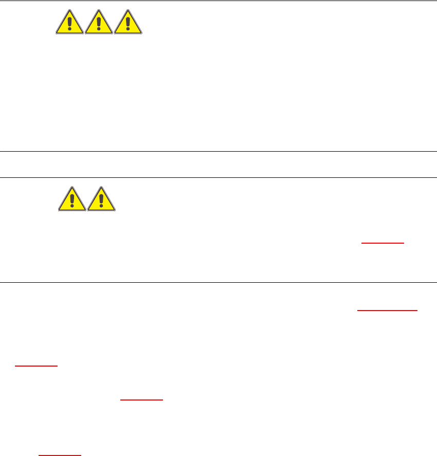
Key for Fig. 8.5.1
:
1. Component table in top position
2. Fasteners for bellows cylinder: 2 socket hex head cap screws M 8 x 50
3. Component table plate
4. Bellows cylinders
5. Bellow cylinder fasteners: 2 washers, 8.4 DIN 125-A, 2 socket hex head cap screws M 8 x 16
6. Quick-release coupling, compressed air supply 5 bar
Service Manual HS-60 8 Movable Component Changeover Table
03/2003 US Issue 8.5 Resolving problems
333
Fig. 8.5.1 Exchanging the bellows cylinder(s)