Service Manual HS60.pdf - 第335页
Se rv ic e Ma nu al HS- 6 0 8 M o va bl e C ompo ne nt C han ge ov er Ta ble 03/ 2 003 U S Iss ue 8. 5 R esol vi ng prob le ms 333 Fig. 8.5 .1 Exc hangi ng the b ellow s cyli nder( s)
8 Movable Component Changeover Table Service Manual HS-60
8.5 Resolving problems 03/2003 US Issue
332
8.5.2 Exchanging the Bellows Cylinder
DANGER
In exceptional cases, a faulty bellows cylinder may prevent the component table from being lifted
and therefore from being disconnected.
If this occurs, contact Siemens SMD Service and discuss how to proceed, taking safety consider-
ations into account.
The table is very heavy and the jammed component table may be released suddenly while it is
being lifting manually, posing a high risk of injury by crushing. 8
WARNING
Parts of your body may be crushed, pinched or severed by the component changeover table!
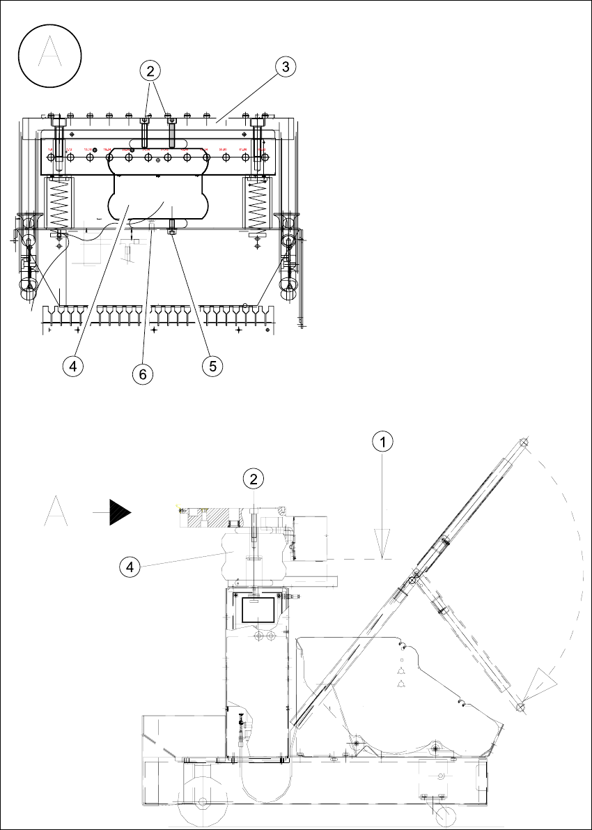
The component table must be in the top position (= position after disconnecting, Fig. 8.5.1
) when
exchanging the bellows cylinder. The component table is mechanically held securely in the „top“
position - even without the help of the bellows cylinder. 8
The component changeover table is dismantled and prepared, as described in Section 8.5.1
. 8
Æ Disconnect the pneumatic hose at the quick-release coupling of the faulty bellows cylinder (see
Fig. 8.5.1
-> 4, 6).
Æ Undo the screws fastening the faulty bellows cylinder from the component table top and bottom
(total of 3 screws, see: Fig. 8.5.1
-> 2, 5, size 6 Allen wrench). Also remove the washer in-
cluded (see -> 5).
Key for Fig. 8.5.1
:
1. Component table in top position
2. Fasteners for bellows cylinder: 2 socket hex head cap screws M 8 x 50
3. Component table plate
4. Bellows cylinders
5. Bellow cylinder fasteners: 2 washers, 8.4 DIN 125-A, 2 socket hex head cap screws M 8 x 16
6. Quick-release coupling, compressed air supply 5 bar
Service Manual HS-60 8 Movable Component Changeover Table
03/2003 US Issue 8.5 Resolving problems
333
Fig. 8.5.1 Exchanging the bellows cylinder(s)
8 Movable Component Changeover Table Service Manual HS-60
8.5 Resolving problems 03/2003 US Issue
334
Æ Remove the bellows cylinder.
Æ Insert the new bellows cylinder (Item No.: see Section 8.2) and fasten the cylinder securely
from top and bottom (total 3 screws, see Fig. 8.5.1
-> 2, 5).
Æ Connect the pneumatic hose (for 5 bar) to the quick-release coupling of the bellows cylinder
and tighten the hex nut (see Fig. 8.5.1
-> 6).
Æ If you do not have to exchange any further parts, perform the appropriate "Final Steps" (see
Section 8.5.7
).
8.5.3 Exchanging fixed castor(s) and/or guide castor(s)
The component changeover table is dismantled and prepared, as described in Section 8.5.1. 8
WARNING
The component changeover table needs to be laid on its side to remove the fixed castor and/or
guide castor. Two people are required for this as the component changeover table is very heavy.8
Æ Enlist the aid of a 2nd strong person and set the component changeover table on its side. (see
Fig. 8.5.2
-> 1).
Æ Undo the screws fastening the fixed castor and/or guide castor to be exchanged (size 6 Allen
wrench: see Fig. 8.5.2
Æ Install the new guide castor(s) and/or the fixed castor(s) (Item No.: see Section 8.2) and refas-
ten each of them with 4 socket hex head cap screws.
Æ With the aid of a 2nd strong person, set the component changeover table back up.
Secure the component changeover table to prevent it from rolling away by itself.
Æ If you have no further parts to be exchanged, perform the appropriate "Final Steps"
(see Section 8.5.7
)