Service Manual HS60.pdf - 第337页
Se rv ic e Ma nu al HS- 6 0 8 M o va bl e C ompo ne nt C han ge ov er Ta ble 03/ 2 003 U S Iss ue 8. 5 R esol vi ng prob le ms 335 Fig. 8.5 .2 Exc hangi ng f i xe d cast or(s ) a nd/o r guid e castor (s) Key fo r Fig. 8.…
8 Movable Component Changeover Table Service Manual HS-60
8.5 Resolving problems 03/2003 US Issue
334
Æ Remove the bellows cylinder.
Æ Insert the new bellows cylinder (Item No.: see Section 8.2) and fasten the cylinder securely
from top and bottom (total 3 screws, see Fig. 8.5.1
-> 2, 5).
Æ Connect the pneumatic hose (for 5 bar) to the quick-release coupling of the bellows cylinder
and tighten the hex nut (see Fig. 8.5.1
-> 6).
Æ If you do not have to exchange any further parts, perform the appropriate "Final Steps" (see
Section 8.5.7
).
8.5.3 Exchanging fixed castor(s) and/or guide castor(s)
The component changeover table is dismantled and prepared, as described in Section 8.5.1. 8
WARNING
The component changeover table needs to be laid on its side to remove the fixed castor and/or
guide castor. Two people are required for this as the component changeover table is very heavy.8
Æ Enlist the aid of a 2nd strong person and set the component changeover table on its side. (see
Fig. 8.5.2
-> 1).
Æ Undo the screws fastening the fixed castor and/or guide castor to be exchanged (size 6 Allen
wrench: see Fig. 8.5.2
Æ Install the new guide castor(s) and/or the fixed castor(s) (Item No.: see Section 8.2) and refas-
ten each of them with 4 socket hex head cap screws.
Æ With the aid of a 2nd strong person, set the component changeover table back up.
Secure the component changeover table to prevent it from rolling away by itself.
Æ If you have no further parts to be exchanged, perform the appropriate "Final Steps"
(see Section 8.5.7
)
Service Manual HS-60 8 Movable Component Changeover Table
03/2003 US Issue 8.5 Resolving problems
335
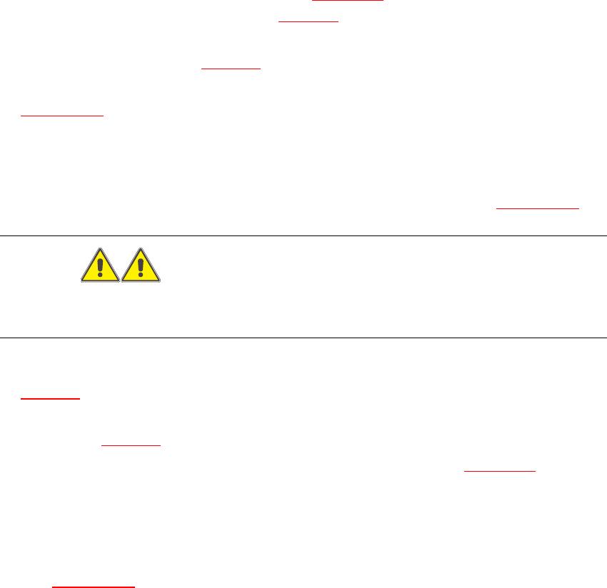
Fig. 8.5.2 Exchanging fixed castor(s) and/or guide castor(s)
Key for Fig. 8.5.2
1. Lay the component table on its side (2nd person required) before removing the rollers.
2. Fixed castors (2 units)
3. 8 Socket hex head cap screws M8 x 16
4. Guide castors (2 units)
5. 8 Socket hex head cap screws M8 x 16
8 Movable Component Changeover Table Service Manual HS-60
8.5 Resolving problems 03/2003 US Issue
336
8.5.4 Exchanging the component table connection cable
8.5.4.1 Power supply cable „component table“
Æ Perform the "Preparatory Steps" (see Section 8.5.1).
It is not necessary to dismantle the feeder modules.
Æ Unplug plugs X13 and X 15 of the communication unit cable.
Æ Disconnect the pneumatic hose.
Æ Disconnect the ground cable at the connection provided.
Æ The ground cable is looped through the component table and fastened at several connections.
To avoid weaving out the complete ground cable, disconnect the cable at the cable shoe.
Æ Open the cord grip and remove the entire cable.
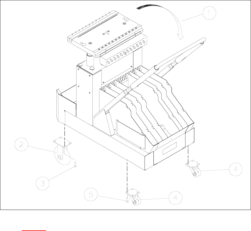
Fig. 8.5.3 Component table cable
Æ Feed the new cable into the cord grip from the top to the bottom.
Æ Plug in the connection cable of the communications unit and reconnect the pneumatic system.
Æ Run the cable and attach cable ties.
Æ If you have no further parts to be exchanged, perform the appropriate "Final Steps",
including using SITEST to check the table function (see Section 8.5.7
).