Service Manual HS60.pdf - 第341页
Se rv ic e Ma nu al HS- 6 0 8 M o va bl e C ompo ne nt C han ge ov er Ta ble 03/ 2 003 U S Iss ue 8. 5 R esol vi ng prob le ms 339 8.5. 6 Ex cha nging the B owde n cabl e 8 Fig. 8.5 . 5 Re mov ing/ inst alli ng the B owd…

8 Movable Component Changeover Table Service Manual HS-60
8.5 Resolving problems 03/2003 US Issue
338
Æ Place the new communications unit on the retaining brackets and tighten the screws to fasten
it.
Æ Reconnect the „component table“ cable at the back of the communications unit housing.
Æ If you have no further parts to be exchanged, perform the appropriate "Final Steps",
including using SITEST to check the table function (see Section 8.5.7
).
Service Manual HS-60 8 Movable Component Changeover Table
03/2003 US Issue 8.5 Resolving problems
339
8.5.6 Exchanging the Bowden cable
8
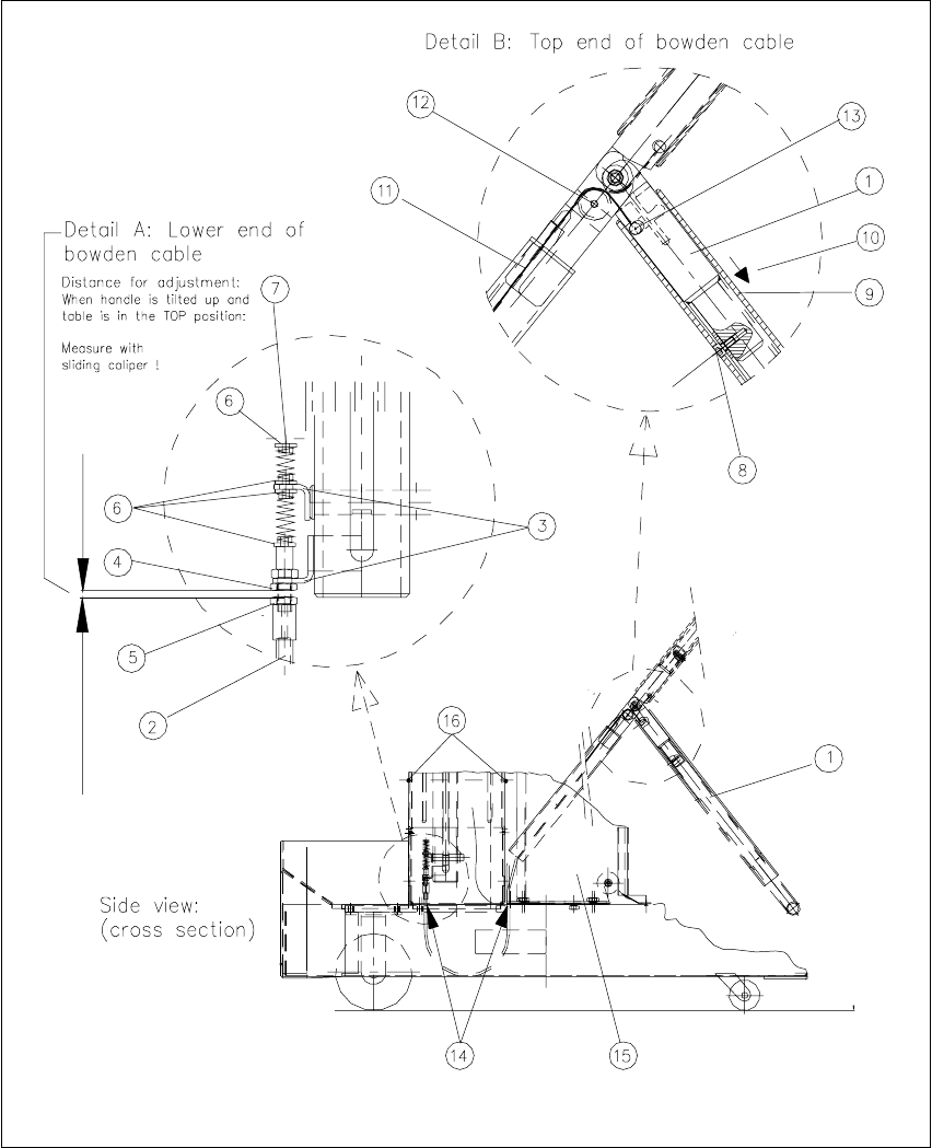
Fig. 8.5.5 Removing/installing the Bowden cable

8 Movable Component Changeover Table Service Manual HS-60
8.5 Resolving problems 03/2003 US Issue
340
Key for Fig. 8.5.5
:
1. Table in starting position "Top". Handle bent
2. Bowden cable, lower end in frame of the component changeover table
3. Retaining bracket, top and bottom
4. M6 hex nut to fasten the Bowden cable
5. M6 hex nut to adjust the Bowden cable
6. Teflon flange
7. End piece of Bowden cable (bottom)
8. Stop of activator tube left / right: one M4 socket hex head cap screw
9. Activator tube
10. Direction in which activator tube is moved
11. Bowden traction cable
12. Little plastic wheel to divert direction of Bowden traction cable
13. End piece of Bowden cable (top)
14. For the Bowden cable: cutouts in the bottom part of the changeover table
15.Tape container
16. Screws to fasten internal cover: two M4 socket head hex cap screws
8
The component changeover table is dismantled and prepared, as described in Section 8.5.1
.
After being disconnected the component table is already in the required position "Top".
8
Æ Use sliding calipers to ascertain the exact distance between the bottom hex nut on the retain-
ing bracket and the adjusting nut for the Bowden cable (see Fig. 8.5.5
: Detail A -> 4, 5) and
record this dimension.
NOTE:
This distance/dimension must be restored after the new Bowden cable is installed. 8
Æ Simultaneously slide the actuator tube up to the stop on both sides and lower the handle (see
Fig. 8.5.5
-> 1, 9).
-> This relieves the tension on the Bowden cable.
Æ It may be necessary to move the tape container to gain access to the 2nd fastening screw for
the internal cover on the frame (see Fig. 8.5.5
-> 16):