Service Manual HS60.pdf - 第342页
8 Mo v ab le Com pon en t C h ange o ve r Ta bl e Serv i ce M an ua l H S- 60 8. 5 R es ol ving pr obl ems 03/ 2 003 U S I ssue 340 Key for Fig. 8. 5.5 : 1. T abl e in starting position "T op". Handle bent 2. B…
Service Manual HS-60 8 Movable Component Changeover Table
03/2003 US Issue 8.5 Resolving problems
339
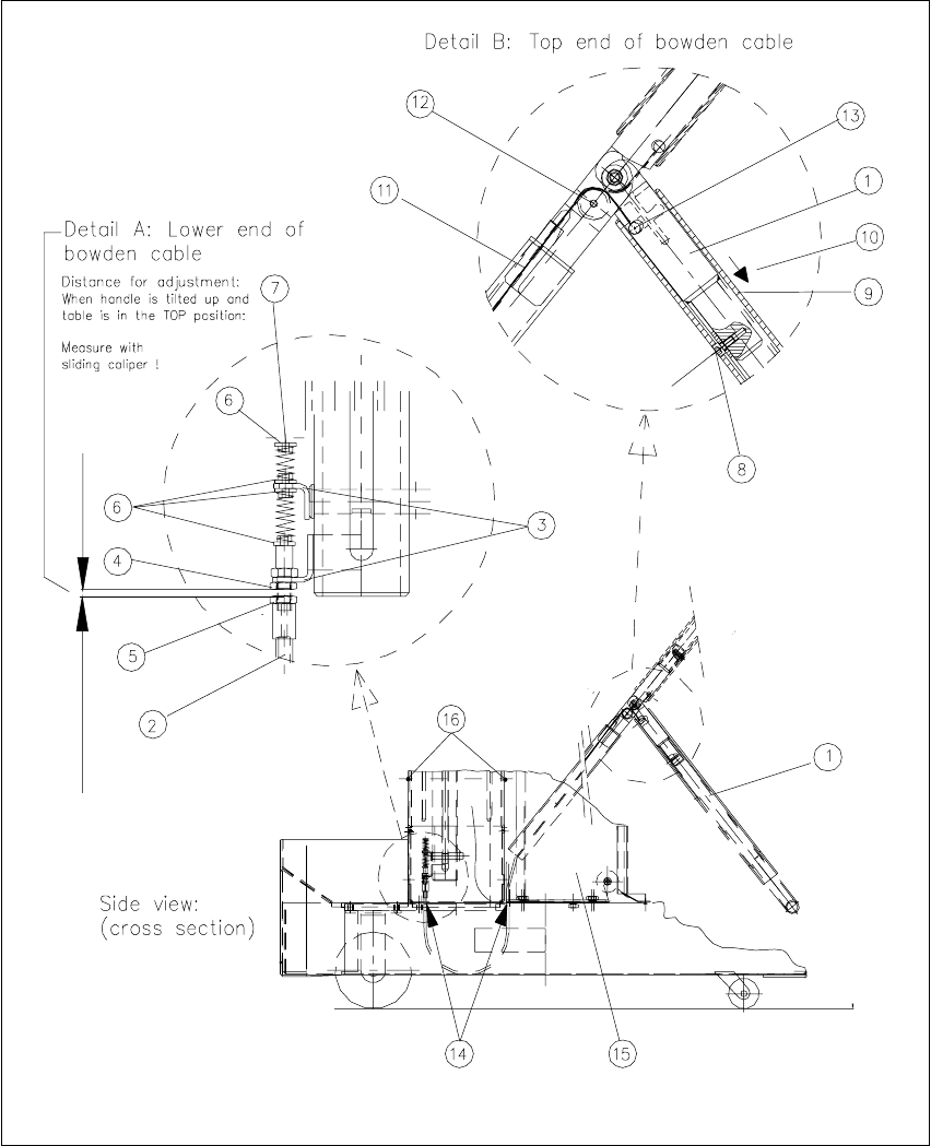
8.5.6 Exchanging the Bowden cable
8
Fig. 8.5.5 Removing/installing the Bowden cable

8 Movable Component Changeover Table Service Manual HS-60
8.5 Resolving problems 03/2003 US Issue
340
Key for Fig. 8.5.5
:
1. Table in starting position "Top". Handle bent
2. Bowden cable, lower end in frame of the component changeover table
3. Retaining bracket, top and bottom
4. M6 hex nut to fasten the Bowden cable
5. M6 hex nut to adjust the Bowden cable
6. Teflon flange
7. End piece of Bowden cable (bottom)
8. Stop of activator tube left / right: one M4 socket hex head cap screw
9. Activator tube
10. Direction in which activator tube is moved
11. Bowden traction cable
12. Little plastic wheel to divert direction of Bowden traction cable
13. End piece of Bowden cable (top)
14. For the Bowden cable: cutouts in the bottom part of the changeover table
15.Tape container
16. Screws to fasten internal cover: two M4 socket head hex cap screws
8
The component changeover table is dismantled and prepared, as described in Section 8.5.1
.
After being disconnected the component table is already in the required position "Top".
8
Æ Use sliding calipers to ascertain the exact distance between the bottom hex nut on the retain-
ing bracket and the adjusting nut for the Bowden cable (see Fig. 8.5.5
: Detail A -> 4, 5) and
record this dimension.
NOTE:
This distance/dimension must be restored after the new Bowden cable is installed. 8
Æ Simultaneously slide the actuator tube up to the stop on both sides and lower the handle (see
Fig. 8.5.5
-> 1, 9).
-> This relieves the tension on the Bowden cable.
Æ It may be necessary to move the tape container to gain access to the 2nd fastening screw for
the internal cover on the frame (see Fig. 8.5.5
-> 16):

Service Manual HS-60 8 Movable Component Changeover Table
03/2003 US Issue 8.5 Resolving problems
341
Æ To do so, loosen the screws fastening the tape container to the frame (4 round head screws
on the container base plate, size 6 Allen wrench),
Æ Move the tape container slightly (or lift out the container).
Æ Loosen the screws fastening the internal cover on the frame (two M4 socket hex head cap
screws: see Fig. 8.5.5
-> 16). Remove the internal cover.
Æ The next step is to relieve the tension on the bottom end piece of the Bowden cable (see Fig.
8.5.5, Detail A):
To do so, loosen the locknut (hex nut: see Fig. 8.5.5
-> 4; size 8 metric open-end wrench) on
the bottom retaining bracket.
Æ Loosen the screw on the bottom of the lowered handle (see Fig. 8.5.5,
Detail B -> 8). The activator tube will slide all the way to the end of the handle (-> 9, 10).
Æ Disengage the Bowden traction cable at the handle’s point of rotation by pulling the little plastic
wheel, including the cable, out toward the inside of the handle (see Fig. 8.5.5
-> 11, 12).
Æ Push the "Top" end piece (using a pin, for example) toward the inside of the handle and out of
the slot (see Fig. 8.5.5
: Detail B -> 13).
Æ From below, weave the Bowden cable out of the cutouts in the frame of the changeover table
(see Fig. 8.5.5
-> 14).
Pull both ends of the Bowden cable down and out of the cutouts in the bottom part of the
changeover table
Æ Install the new Bowden cable (Item No.: see Section 8.2) by executing the steps in reverse or-
der to disassembly:
Æ From below, feed the Bowden cable up into the cutouts in the bottom part of the changeover
table. Run the end with the pressure springs to the retaining brackets and the other end up
through the hole in the handle.
Æ Engage the Bowden cable on the 2 small retaining brackets down in the frame.
Æ To fasten the Bowden cable, tighten the hex nut under the bottom retaining bracket (see
Fig. 8.5.5
: Detail A -> 4).
Æ For the time being, just hand-tighten the hex nut below the hex nut mentioned in the pre-
ceding step (see Fig. 8.5.5
: Detail A -> 5).
Æ Push the "Top" end piece into the slot in the lowered handle (see Fig. 8.5.5: Detail B -> 13).
Æ Lay the top end of the Bowden traction cable into the groove around the circumference of
the little plastic wheel and insert this wheel.
Æ Push the actuator tube back in the direction of the handle’s point of rotation and hold the
actuator tube in this position.
Æ From the bottom of the handle, screw the M4 socket head hex cap screw back in (see Fig.
8.5.5, Detail B -> 8).