Service Manual HS60.pdf - 第37页
Se rv ice M a nu al HS-6 0 2 Ope rati on al saf et y 03/ 200 3 U S Iss ue 2.3 Laser clas sifica tio n 35 W ARNING 2 Never connect the connecting cable f o r the c o mponent trolley to the socket o n the placem ent system…
2 Operational safety Service Manual HS-60
2.3 Laser classification 03/2003 US Issue
34
2.3.5 Safety instructions for docking and undocking the component trolley
.
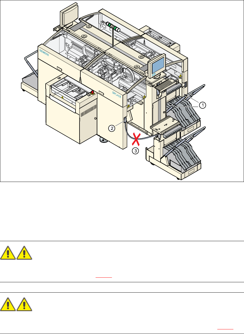
Fig. 2.3 - 2 Safety instructions on the component trolley
WARNING 2
Never reach into the gaps between the component trolley and the placement system frame while
the machine is running (item 1 in Fig. 2.3 - 2).
WARNING 2
The power cable for the component trolley must not be connected to the machine socket, or
pulled out of it, unless the component trolley is docked on the machine (Pos. 2 in Fig. 2.3 - 2).
(1) Vertical gap between the placement system frame and the component trolley
(2) Plug for connecting the component trolley cable
(3) Connecting cable for compressed air and main power supply to the component trolley
Service Manual HS-60 2 Operational safety
03/2003 US Issue 2.3 Laser classification
35
WARNING 2
Never connect the connecting cable for the component trolley to the socket on the placement
system and then operate the component trolley outside the machine via the compressed air con-
trol unit (item 3 in Fig. 2.3 - 2)
WARNING DANGER OF CRUSHING
You must always take hold of the bar with both hands whenever you want to move the component
trolley into the machine. 2
2.3.6 Safety instructions for changing the table height of component trolleys
WARNING RISK OF CRUSING CRUSHING
The component trolley must only be converted to modify the default ta-
ble height by trained Service personnel.
Act with considerable care during the conversion process since the sys-
tem contains large weights or compression springs (potential energy).2
Converting the component trolley to suit a different line height 2
Æ Use the placement system’s pneumatic controller to raise the table bed. Then insert a 120mm
spacer block between the table bed and crossbeam, and lower the bed onto the block.
Æ Dismantle the internal paneling.
Æ Swivel the handle down. The latching disk swivels down as well.
Æ Set the screw to the desired dimension and lock in place with the locknut.
PLEASE NOTE:
If you cannot loosen the adjusting screw far enough, the crossbeam must be raised. 2
Æ Fix the lifting device to the crossbeam.
Æ Carefully open the crossbeam clamp.
Æ Raise the crossbeam until the end of the tube projects approx. 1mm out of the clamp.
Æ Tighten the crossbeam clamp.
Æ Then turn the adjusting screw to the desired dimension and lock in place with the locknut.

2 Operational safety Service Manual HS-60
2.3 Laser classification 03/2003 US Issue
36
Æ Swivel the component trolley handle up. The latching disk will also swivel up.
PLEASE NOTE:
If you cannot swivel the latching disk up to its end position, the cross-beam must be raised. 2
Æ Fix the lifting device to the crossbeam.
Æ Carefully open the crossbeam clamp.
Æ Raise the crossbeam until the end of the tube projects approx. 1mm out of the clamp.
Æ Tighten the crossbeam clamp.
Æ Then turn the adjusting screw to the desired dimension and lock in place with the locknut.
Æ Then carefully open the crossbeam clamp.
Æ Lower the crossbeam until the adjusting screw comes into contact with the latching disk.
Æ Tighten the crossbeam clamp.
Æ Then check the distance between the crossbeam and floor.
Æ Refit the internal paneling.
Æ Raise the table bed and remove the spacer block.
2.3.7 Safety instructions for processing capacitors based on powdered metal
There is a risk associated with processing capacitors based on powdered metal (e.g. tantalum).
The risk is that
– an exothermic reaction, i.e. a sudden buildup of heat, may occur, if these components are dam-
aged. If the ambient conditions are unfavorable, and depending on the capacitance, this
buildup of heat can cause damage.
– This effect can occur when these components are cut.
Please contact your suppliers to clarify whether the components that you handle are affected.
In extremely rare cases, this risk can occur in the tape cutter of SIPLACE machines, with the
remote possibility of causing a smoldering fire in the waste tape.
The ambient conditions are unfavorable if:
(1) The components remain on the tape while the set tape cycle is checked (since the operator
can cycle the feeder onward without removing components during this check).
(2) The components remain on the tape, e.g. due to a tear in the cover foil.
(3) The components remain on the tape, and the components or tape do not conform to the
specification, thus increasing the pickup error rate.