Service Manual HS60.pdf - 第52页
2 O per ati onal sa fety S er vice Ma nual H S- 60 2.4 S afe ty equi pment 03/ 200 3 U S Iss ue 50 – 24 V operating voltage is switched to the used tape cut ters . The m achine i s t hen ready for use. 2
Service Manual HS-60 2 Operational safety
03/2003 US Issue 2.4 Safety equipment
49
If the safety loop is closed, 24 VDC is present at channels 2 and 3 of the PCC. The two green
LEDs for channels 2 and 3 light up in addition to the green Power ON LED. 2
2.4.4.2 Structure of the signalling circuit
The six signalling contacts for the covers are connected in parallel and form the "cover signal" cir-
cuit. If one or more covers are opened, the contacts close - 24 V signal reaches the CAN bus and
signals that one of the covers is open. 2
The two signalling contacts for the EMERGENCY-STOP mushroom-head push-button are con-
nected in parallel and form the "EMERGENCY-STOP mushroom-head push-button signal" circuit.
When an EMERGENCY-STOP mushroom-head push-button is pressed, a 24 V signal is sent to
the CAN bus and signals that one of the EMERGENCY-STOP mushroom-head push-buttons has
been pressed. 2
The four signalling contacts for the push-button flaps are connected in parallel. They form the
"Flap signal" circuit. If one or more flaps is raised, a 24 V signal is applied to the CAN bus and
signals that one of the cover flaps is not closed. 2
The four signalling contacts for the CO trolleys are connected in series and form the "Component
table" signal loop. If a CO trolley is missing, a 0 V signal is sent to the CAN bus. If all trolleys are
connected, the signal is approximately 16 V. 2
2.4.4.3 Description of the functions of the safety circuit
The following conditions must be fulfilled before the placement system can be started or operated:2
– all four CO trolleys must be docked and connected.
– all covers - four over the gantries, one over the PCB input belt and one over the output belt -
must be closed.
– both EMERGENCY-STOP mushroom-head push-buttons must be released.
– all four flaps over the push-buttons for raising and lowering the CO trolley must be closed.
– the minimum operating pressure must have been reached.
– the software Enable signal must have been given, thus activating the safety circuit.
– The power supply must be sending 24 V to the start buttons and the protective contactor com-
bination.
– If one of the start buttons is now pressed, the protective contactor combination PCC will switch
and activate the following components:
– 200 V link voltage for the servo amplifiers for the gantry axes
– 100 V link voltage for the star axes
– operating voltage for the lifting table motors
– the servo unit will receive a "Servo Enable" signal for the servo amplifier.
– 34 V operating voltage is switched to the CO trolleys
2 Operational safety Service Manual HS-60
2.4 Safety equipment 03/2003 US Issue
50
– 24 V operating voltage is switched to the used tape cutters.
The machine is then ready for use. 2
Service Manual HS-60 2 Operational safety
03/2003 US Issue 2.4 Safety equipment
51
2
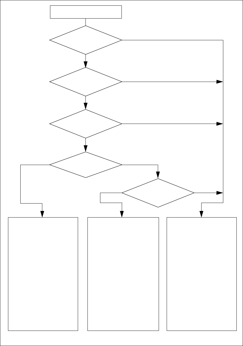
Fig. 2.4 - 7 Safety circuits
Compressed air
min. 0.5 MPa
(5.0 bar)?
No
Start button pressed
Emerg. stop
mushroom-head push-but-
ton pressed?
Protective cover open ?
Key switch
closed (positionI)?
No
Component table
safety circuit
interrupted?
Yes
No
No
Yes
Yes
No
Active
PCC*) yes
voltage
Y-axis 200 V
X-axis 200 V
Star axis 100 V
DP-axis 30 V
Z-axis 30 V
Active
PCB conveyor yes
Lifting table yes
PCB clamping yes
Width adjustment yes
Laser light barrier yes
Used tape cutter yes
Yes
Active
PCC*) no
voltage
Y-axis 0 V
X-axis 0 V
Star axis 6 V
DP-axis 30 V
Z-axis 30 V
Active
PCB conveyor yes
Lifting table no
PCB clamping no
Width adjustment yes
Laser light barrier no
Used tape cutter no
Active
PCC*) no
voltage
Y-axis 0 V
X-axis 0 V
Star axis 10 V
DP-axis 30 V
Z-axis 30 V
Active
PCB conveyor no
Lifting table no
PCB clamping no
Width adjustment no
Laser light barrier no
Used tape cutter no
*) PCC protective contactor combination
yes