Service Manual HS60.pdf - 第56页
2 O per ati onal sa fety S er vice Ma nual H S- 60 2.5 R esi dual voltag es and di schar ge t imes i n t he mach ine 03/ 2003 US Is sue 54 F ig. 2. 5 - 1 T es t s o ck ets o n t he v ol tmet er u nit in t he s erv o un i…
Service Manual HS-60 2 Operational safety
03/2003 US Issue 2.5 Residual voltages and discharge times in the machine
53
2.5 Residual voltages and discharge times in the
machine
If the EMERGENCY-STOP mushroom-head push-button is pressed or the placement system is
switched off, the 200 V link voltage for the gantry axes and the 100 V link voltage for the star axes
are discharged to harmless residual voltages in a very short time.
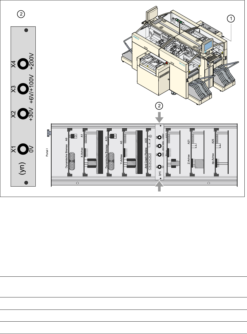
The voltages can be tapped off at test sockets X1 - X4 on the voltage measuring unit in the servo
unit. 2
WARNING 2
The placement system is supplied with 3 x 204 VAC (US version), 3 x 230 VAC, 3 x 380 VAC,
3 x 400 VAC or 3 x 415 VAC ± 5 %, 50/60 Hz main power voltage. This means that some parts of
the system carry potentially lethal voltages - even when switched off at the main power
switch.Death, serious injury or considerable damage may result if this automatic placement sys-
tem is handled incorrectly.
Æ Always follow the applicable accident prevention and DIN regulations (particularly DIN EN 60
204, part 1).
Æ The guard over the servo unit must ONLY be opened by appropriately qualified and trained
personnel.
2 Operational safety Service Manual HS-60
2.5 Residual voltages and discharge times in the machine 03/2003 US Issue
54
Fig. 2.5 - 1 Test sockets on the voltmeter unit in the servo unit
(1) Position of the servo unit
(2) Voltage measuring unit on the servo unit
2.5.1 Operating voltages, residual voltages and discharge times after pressing
the emergency stop mushroom-head push-button
2
Test sockets X2, X3, X4
measured to X1 (GND) Voltage in normal mode
Residual voltage after
EMERG. STOP Discharge times
X2 + 30 VDC + 30 VDC -
X3 + 100 VDC < 10 VDC 50 sec.
X4 + 200 VDC < 10 VDC 7 sec.
Service Manual HS-60 2 Operational safety
03/2003 US Issue 2.6 Disabling the compressed air supply and discharging the pressure
55
2.5.2 Residual voltages and discharge times after switching off at the main switch
CAUTION To avoid losing data, evaluate the following criteria before switching off
your automatic placement system (apart from in emergencies): 2
– – Has the placement system finished transmitting machine, setup and panel data?
– – Has the placement system finished processing the PCB?
– – Has the placement system completed the run-up phase?
2.6 Disabling the compressed air supply and discharg-
ing the pressure
The compressed air working pressure is set to 0.55 MPa (5.5 bar). The position of the compressed
air unit is indicated by item 4 in Fig. 2.6 - 1
. The compressed air supply to the machine can be
interrupted using the shutoff valve (item 1 in Fig. 2.6 - 1
). 2
Æ Open the protective door.
Æ Turn the lever on the shutoff valve (item 1 in Fig. 2.6 - 1) from the vertical to the horizontal po-
sition.
Æ Watch the working pressure gauge and the pressure gauge for the compressed air supply to
the stopper (items 2 and 3 in Fig. 2.6 - 1
). When the automatic placement system is switched
on, the pressure discharges to 0 MPa (0 bar) within 1 minute.
CAUTION
When the machine is switched on, do not use the stop valve to interrupt the compressed air sup-
ply for more than 30 minutes. If you need to shut off the pneumatic system for longer in order to
carry out maintenance or servicing work, you must switch the placement system off at the main
switch and disconnect it from the power supply.
Test sockets X2, X3, X4
measured to X1 (GND)
Residual voltages when main
power switch is off Discharge times
X2 < 10 VDC < 2 sec.
X3 < 10 VDC < 50 sec.
X4 < 10 VDC < 7 sec.