Service Manual HS60.pdf - 第57页
Se rv ice M a nu al HS-6 0 2 Ope rati on al saf et y 03/ 2003 US Is sue 2.6 D isab lin g the co mpress ed ai r s uppl y and di scha rging t he pres sure 55 2.5. 2 Residual vo lt ag es and disch ar ge tim es af ter switc …
2 Operational safety Service Manual HS-60
2.5 Residual voltages and discharge times in the machine 03/2003 US Issue
54
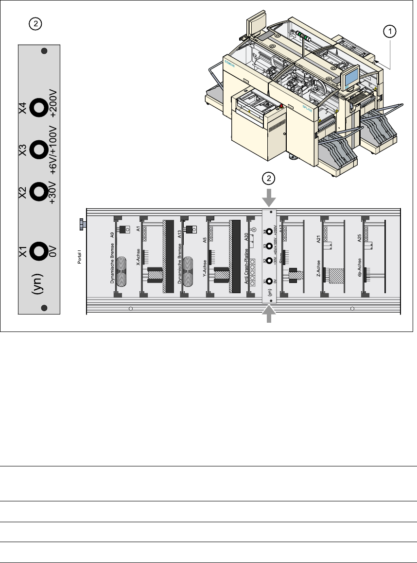
Fig. 2.5 - 1 Test sockets on the voltmeter unit in the servo unit
(1) Position of the servo unit
(2) Voltage measuring unit on the servo unit
2.5.1 Operating voltages, residual voltages and discharge times after pressing
the emergency stop mushroom-head push-button
2
Test sockets X2, X3, X4
measured to X1 (GND) Voltage in normal mode
Residual voltage after
EMERG. STOP Discharge times
X2 + 30 VDC + 30 VDC -
X3 + 100 VDC < 10 VDC 50 sec.
X4 + 200 VDC < 10 VDC 7 sec.
Service Manual HS-60 2 Operational safety
03/2003 US Issue 2.6 Disabling the compressed air supply and discharging the pressure
55
2.5.2 Residual voltages and discharge times after switching off at the main switch
CAUTION To avoid losing data, evaluate the following criteria before switching off
your automatic placement system (apart from in emergencies): 2
– – Has the placement system finished transmitting machine, setup and panel data?
– – Has the placement system finished processing the PCB?
– – Has the placement system completed the run-up phase?
2.6 Disabling the compressed air supply and discharg-
ing the pressure
The compressed air working pressure is set to 0.55 MPa (5.5 bar). The position of the compressed
air unit is indicated by item 4 in Fig. 2.6 - 1
. The compressed air supply to the machine can be
interrupted using the shutoff valve (item 1 in Fig. 2.6 - 1
). 2
Æ Open the protective door.
Æ Turn the lever on the shutoff valve (item 1 in Fig. 2.6 - 1) from the vertical to the horizontal po-
sition.
Æ Watch the working pressure gauge and the pressure gauge for the compressed air supply to
the stopper (items 2 and 3 in Fig. 2.6 - 1
). When the automatic placement system is switched
on, the pressure discharges to 0 MPa (0 bar) within 1 minute.
CAUTION
When the machine is switched on, do not use the stop valve to interrupt the compressed air sup-
ply for more than 30 minutes. If you need to shut off the pneumatic system for longer in order to
carry out maintenance or servicing work, you must switch the placement system off at the main
switch and disconnect it from the power supply.
Test sockets X2, X3, X4
measured to X1 (GND)
Residual voltages when main
power switch is off Discharge times
X2 < 10 VDC < 2 sec.
X3 < 10 VDC < 50 sec.
X4 < 10 VDC < 7 sec.
2 Operational safety Service Manual HS-60
2.6 Disabling the compressed air supply and discharging the pressure 03/2003 US Issue
56
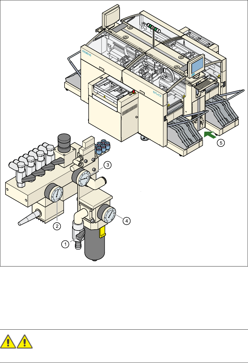
Fig. 2.6 - 1 Compressed air unit on the automatic placement system
WARNING
NEVER detach compressed air lines while they are still pressurized. Risk of injury. 2
(1) Shutoff valve lever in the CLOSED position
(2) Working pressure gauge
(3) Pressure gauge for the component table operating pressure
(4) Input pressure gauge
(5) Position of the compressed air unit on the placement system behind the safety door