Service Manual HS60.pdf - 第62页
2 O per ati onal sa fety S er vice Ma nual H S- 60 2. 7 E ner gy s ta te of th e m a ch ine aft er sw i tc hin g of f a t t he ma in p owe r s w it ch 0 3/2 00 3 US I ssue 60 2.7. 1 Placement sy stem switch ed off at the…
Service Manual HS-60 2 Operational safety
03/2003 US Issue 2.7 Energy state of the machine after switching off at the main power switch
59
2
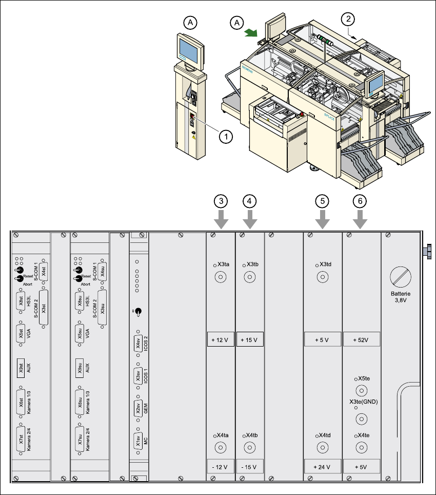
Fig. 2.7 - 2 Position of control unit and main power switch
2
(1) Main power switch
(2) Control unit
(3) Power supply unit ± 12 V-
(4) Power supply unit ± 15 V-
(5) Power supply unit + 5 V-/+ 24 V-
(6) Power supply unit + 5 V-/+ 52 V-
2 Operational safety Service Manual HS-60
2.7 Energy state of the machine after switching off at the main power switch 03/2003 US Issue
60
2.7.1 Placement system switched off at the main power switch, but still connected
The following table specifies the voltages of assemblies when the automatic placement system is
switched off at the main switch, but still connected to the mains supply. 2
WARNING 2
The following components still carry potentially lethal voltages even if the main power switch is
switched off: 2
– cable connection terminals 1, 3, and 5 of the S1 main power switch
– main power filter Z1
– BU1 service socket
– F1 automatic circuit breaker for the service socket
– The color of all individual wires, which still carry potentially lethal voltages even if the main
power switch is switched off, is brown.
Assembly Voltage
Main power filter Z1
Terminals L1, L2, L3
3 x 204 VAC
3 x 230 VAC
3 x 380 VAC
3 x 400 VAC
3 x 415 VAC
BU1 service socket
115 VAC
130 VAC
220 VAC
230 VAC
240 VAC
F1
automatic circuit breaker
115 VAC
130 VAC
220 VAC
230 VAC
240 VAC
Service Manual HS-60 2 Operational safety
03/2003 US Issue 2.7 Energy state of the machine after switching off at the main power switch
61
2.7.2 Placement system switched off at the main power switch and disconnected
The automatic placement system is unpowered, apart from slight residual voltages in the servo
unit. 2
2.7.3 Compressed air conditions in the machine after switching off at the
main power switch
When the system is switched off at the main power switch (item 1 in Fig. 2.7 - 1) or if the power
supply fails, the electrically-controlled main valve Y1 of the compressed air unit closes (item 3 in
Fig. 2.7 - 1
, page ). The pressure will drop to 0 MPa (0 bar) within 5 seconds. 2
S1 main power switch
Terminals 1, 3, 5
3 x 204 VAC
3 x 230 VAC
3 x 380 VAC
3 x 400 VAC
3 x 415 VAC
Servo unit (see item 5 in Fig. 2.7 - 2
)
Test socket X2
Test socket X3
Test socket X4
GND X1
< 10 VDC
< 10 VDC
< 10 VDC
Control unit (see items 3, 4, 5, and 6 in
Fig. 2.7 - 2
)
Test socket + 12 VDC (x3ta)
Test socket 12 VDC (x4ta)
Test socket + 15 VDC (x3tb)
Test socket -15 VDC (x4tb)
Test socket + 5 VDC (x3td)
Test socket + 24 VDC (x4td)
Test socket + 52 VDC (x5te)
Test socket + 5 VDC (x4te)
GND (x3td)
0 VDC
0 VDC
0 VDC
0 VDC
0 VDC
0 VDC
0 VDC
0 VDC