Service Manual HS60.pdf - 第70页
2 O per ati onal sa fety S er vice Ma nual H S- 60 2.9 E SD gu idel ines 03/ 200 3 U S Iss ue 68
Service Manual HS-60 2 Operational safety
03/2003 US Issue 2.9 ESD guidelines
67
Always place the modules on a conductive surface (table with an ESD coating, conductive ESD
foam, ESD bag or container). 2
Do not bring modules near visual display units, monitors or televisions. Keep them at least 10 cm
away from the screen. 2
2.9.4 Measurements and modifications to ESD modules
Do not take measurements on such modules unless 2
– the measuring device is earthed (e.g. via PE conductors) or
– you discharge the measuring head just before taking measurements with a potential-free mea-
suring device (e.g. by touching an unpainted metal part of the controller casing).
Æ Always use an earthed soldering iron if you carry out any soldering work.
2.9.5 Dispatching ESD modules
Æ Always store modules and components in conductive packaging (e.g. metallized plastic bags
or metal sleeves) and dispatch them in conductive packaging.
If the packaging is not conductive, place the modules in a conductive envelope before packag-
ing. (Use ESD bags, domestic aluminum foil or paper, for example. NEVER use plastic bags
or film). 2
Æ If the module has integral batteries, ensure that the conductive packaging does not touch or
short-circuit the battery terminals and, if necessary, first cover the terminals with insulating tape
or material.
2
2 Operational safety Service Manual HS-60
2.9 ESD guidelines 03/2003 US Issue
68
HS-60 Service Manual 3 Power Supply
03/2003 US Issue 3.1 Position of the modules
69
3 Power Supply
3.1 Position of the modules
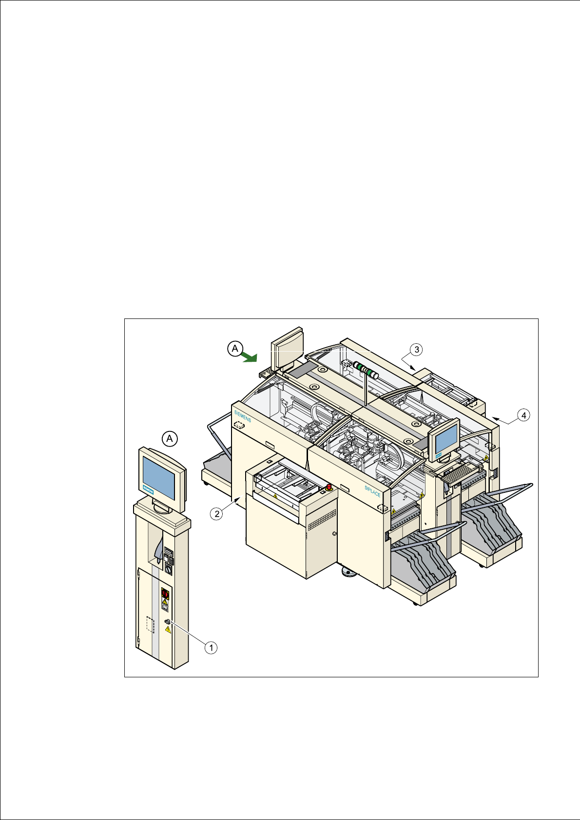
The diagram below shows the position of the modules that generate or distribute the power
needed to operate the placement system: 3
– Power supply unit (Pos. 1)
– Main distribution unit (Pos. 2)
– Control unit (Pos. 3)
– Servo unit (Pos. 4)
3
Fig. 3.1 - 1 Position of the power supply modules