Service Manual HS60.pdf - 第71页
HS -60 Se rvic e Manu al 3 P owe r Su pply 03/ 200 3 U S Iss ue 3.1 Posit ion of th e modu les 69 3 Power Supply 3.1 Positi on of the m odules The diagram below shows the position of the m odules that generate or distrib…
2 Operational safety Service Manual HS-60
2.9 ESD guidelines 03/2003 US Issue
68
HS-60 Service Manual 3 Power Supply
03/2003 US Issue 3.1 Position of the modules
69
3 Power Supply
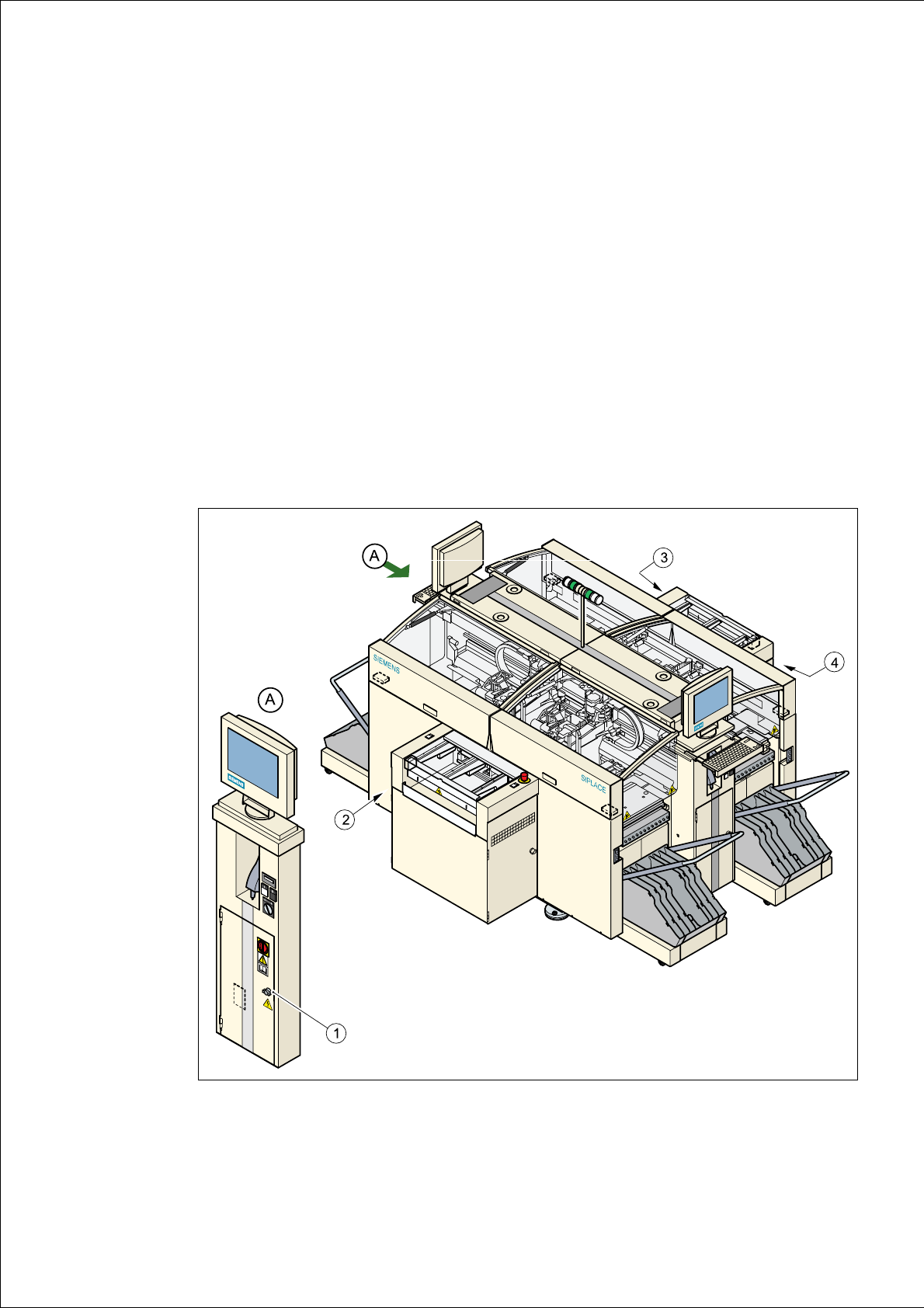
3.1 Position of the modules
The diagram below shows the position of the modules that generate or distribute the power
needed to operate the placement system: 3
– Power supply unit (Pos. 1)
– Main distribution unit (Pos. 2)
– Control unit (Pos. 3)
– Servo unit (Pos. 4)
3
Fig. 3.1 - 1 Position of the power supply modules

3 Power Supply HS-60 Service Manual
3.2 Power supply unit 03/2003 US Issue
70
3.2 Power supply unit
3.2.1 Supply voltages
The power supply unit is located in the left-hand middle section of the placement system. A lock-
able door prevents access to the unit. 3
The power supply unit provides the following supply voltages: 3
– 200 VDC for the servo amplifiers of the x and y axes
– 100 VDC/4 VDC for the servo amplifiers of the star
– 30 VDC for the servo amplifiers the z and dp axes
– 52 VDC for the DC/DC converters in the control unit
– 40 VDC for the component tables and the PCB handling system
– 10 VDC for the component tables
– 3 x 230 VAC for the lifting table motors of the single or dual conveyor (option)
– 230 VAC for the UPS for the station computer and monitors
For the service socket 3
PLEASE NOTE: The service socket can only be used if the placement system is con-
nected to the main power supply with a 5-conductor cable (L1, L2, L3, N, PE). 3
230 VAC (Europe) Input 3 x 400 VAC
115 VAC (U. S. A.) Input 3 x 204 VAC
130 VAC (other) Input 3 x 230 VAC
220 VAC (other) Input 3 x 380 VAC
240 VAC (other) Input 3 x 415 VAC