Service Manual HS60.pdf - 第92页
3 Pow er S up ply H S-6 0 S erv ic e Manu al 3.9 R epl acin g p arts 03/2 00 3 US I ss ue 90
HS-60 Service Manual 3 Power Supply
03/2003 US Issue 3.9 Replacing parts
89
3
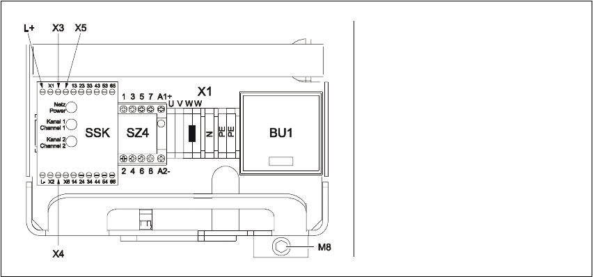
Fig. 3.9 - 1 M8 hexagon socket-head screw for fixing the units
3.9.3 What to do on completion of the servicing work
Æ Fit the power supply unit and fix in place with the M8 hexagon socket-head screw
Æ Make sure that you do not squash the cable when inserting the board
Æ Lock the safety doors
Æ Remove the key and keep in a safe place
3
3
Ziehen Sie den Einschub
vorsichtig heraus
A
chten Sie darauf, dass die
Kabel nicht gequetscht werden
Beschädigen Sie Isolierung
nicht
3 Power Supply HS-60 Service Manual
3.9 Replacing parts 03/2003 US Issue
90
HS-60 Service Manual 4 Gantries
03/2003 US Issue 4.1 Overview
91
4Gantries
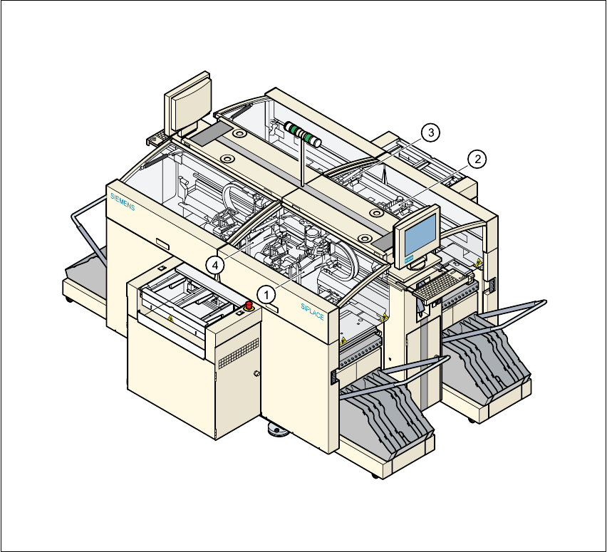
4.1 Overview
The placement system is equipped with four gantries. These enable the four collect&place heads
to be positioned in the x and y directions with great accuracy and independently of one another.4
4
Fig. 4.1 - 1 Gantries on the placement system
Key
(1) Gantry 1 (2) Gantry 2
(3) Gantry 3 (4) Gantry 4