VI User Manual.pdf - 第107页
.TST file creation Vision 2007 4.10 User Manua l Rev 01 4 - 33 4.8.4.8 Joker zone manua l creation First step 1. Display the zones. 2. Select the Joker zone icon on the floating menu. 3. Click on the component that requi…
.TST file creation
4 - 32 Vision 2007 4.10 User Manual Rev 01
4.8.4.6 Manual zones creation
Floating menu allows a manual creation of the different zones.
4.8.4.7 Centered zone manual creation
1.
In the .tst edition tools bar, click on
Display zones
button to display all acquisition zones.
2. On the floating menu, select the Centered zone icon .
3. Click on the component that require a centered zone.
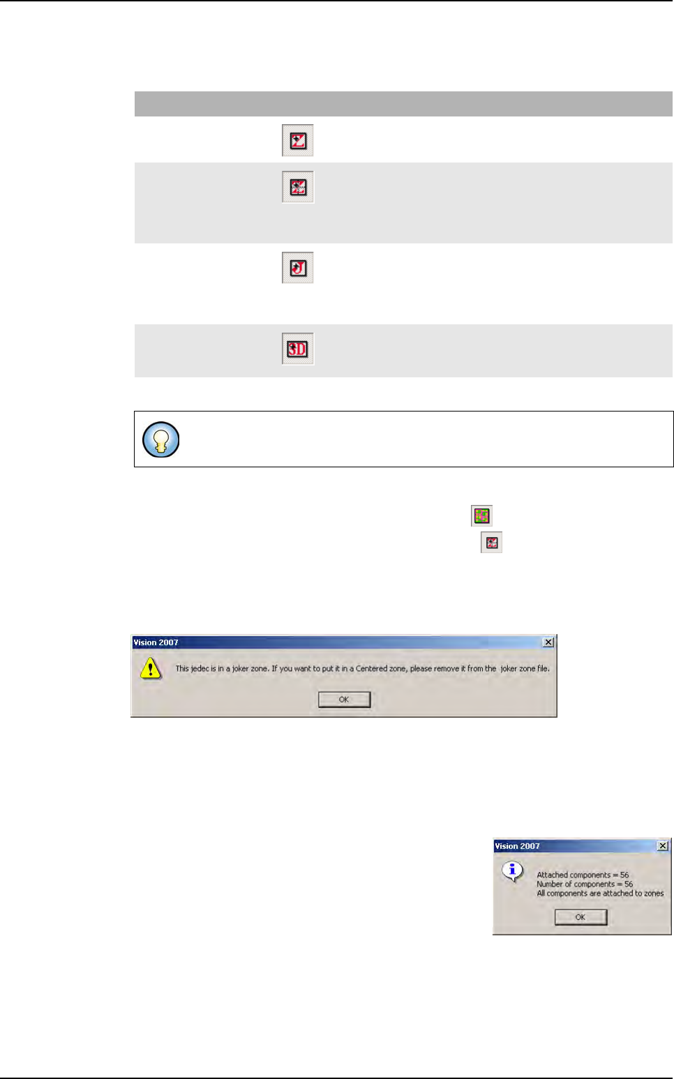
Case 1: the component is already defined in the zone file as a component associated to
a joker zone. An error message appears.
.
Remove the jedec from the zones .dsc file before to create a joker zone on this component.
Case 2: the component is a component that needed a multi-zone. The operator cannot
create a centered zone on multi-zone component (no message).
Case 3: the component is not defined in the zone file or the zone file is empty. The Zone
edition window is displayed, adjust the light settings.
Click on OK to validate settings, the zones file is updated
with the new Jedec name. An information message will
appear confirming the re-attachment of the components.
Case 4: the component is already defined in the zone file as a component associated to
a centered zone. The Zone edition window is displayed, adjust the light settings.
Click on OK to validate your settings, the zones file is updated with the new Jedec name.
A second zone will be created associated to the component.
Zone type Icon Action description
Standard zone The operator can click every where on the .tst file, the components
included in the zone area will be attached to the zone.
Centered zone The operator must click on a chosen component, the components
included in the zone area will be attached to the zone.
The chosen component must be either defined in the zone file as a
centered component or either not defined at all. It cannot be a multi-
zone or a component already defined in a joker zone.
Joker zone The operator must click on a chosen component, only this compo-
nent will be attached to the zone.
The chosen component must be either defined in the zone file as a
joker component or either not defined at all. It cannot be a multi-
zone or a component already defined in a centered zone.
Scan zone The operator can click everywhere on the .tst file, the components
included in the zone area will be attached to the zone. The area will
depend on the width set.
In the floating menu, the left menu allow the moving and the selection of a zone.
Zones creation
.TST file creation
Vision 2007 4.10 User Manual Rev 01 4 - 33
4.8.4.8 Joker zone manual creation
First step
1. Display the zones.
2. Select the Joker zone icon on the floating menu.
3. Click on the component that require a joker zone.
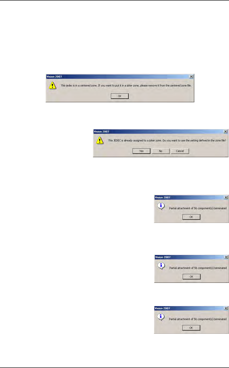
Case 1: the component is already defined in the zone file as a component associated to
a centered zone. An error message will appear.
Remove the jedec from the zones .dsc file before creating a Joker zone on this component.
Case 2: the component is a component that needed a multi-zone. The operator cannot
create a joker zone on multi-zone component (no message).
Case 3: the compo-
nent is already de-
fined in the zone file
as a component as-
sociated to a joker
zone. An interroga-
tive message will appear
Case 3.1: Click on Yes. The Zone edition window is displayed with the light settings of
the jedec defined in the zone file. Adjust the light settings if necessary.
Click on OK to validate your settings.
Click on UPDATE if you want the zones file to be
updated. An information message will appear con-
firming the re-attachement of the components.
Case 3.2: Click on NO. The zone edition window is displayed with the light settings of the
jedec defined in the default.ini file. Adjust the light settings if necessary.
Click on OK to validate your settings.
Click on UPDATE if you want the zones file to be
updated. An information message will appear con-
firming the re-attachement of the components.
Case 4: the component has already a joker zone defined. The zone edition window is
displayed. Adjust the light settings.
Click on OK to validate your settings, the zones file
is updated with the new Jedec name and its re-
quired light adjustments. The new zone will re-
place the previous one. An information message
will appear confirming the re-attachement of the
components.
Zones creation
.TST file creation
4 - 34 Vision 2007 4.10 User Manual Rev 01
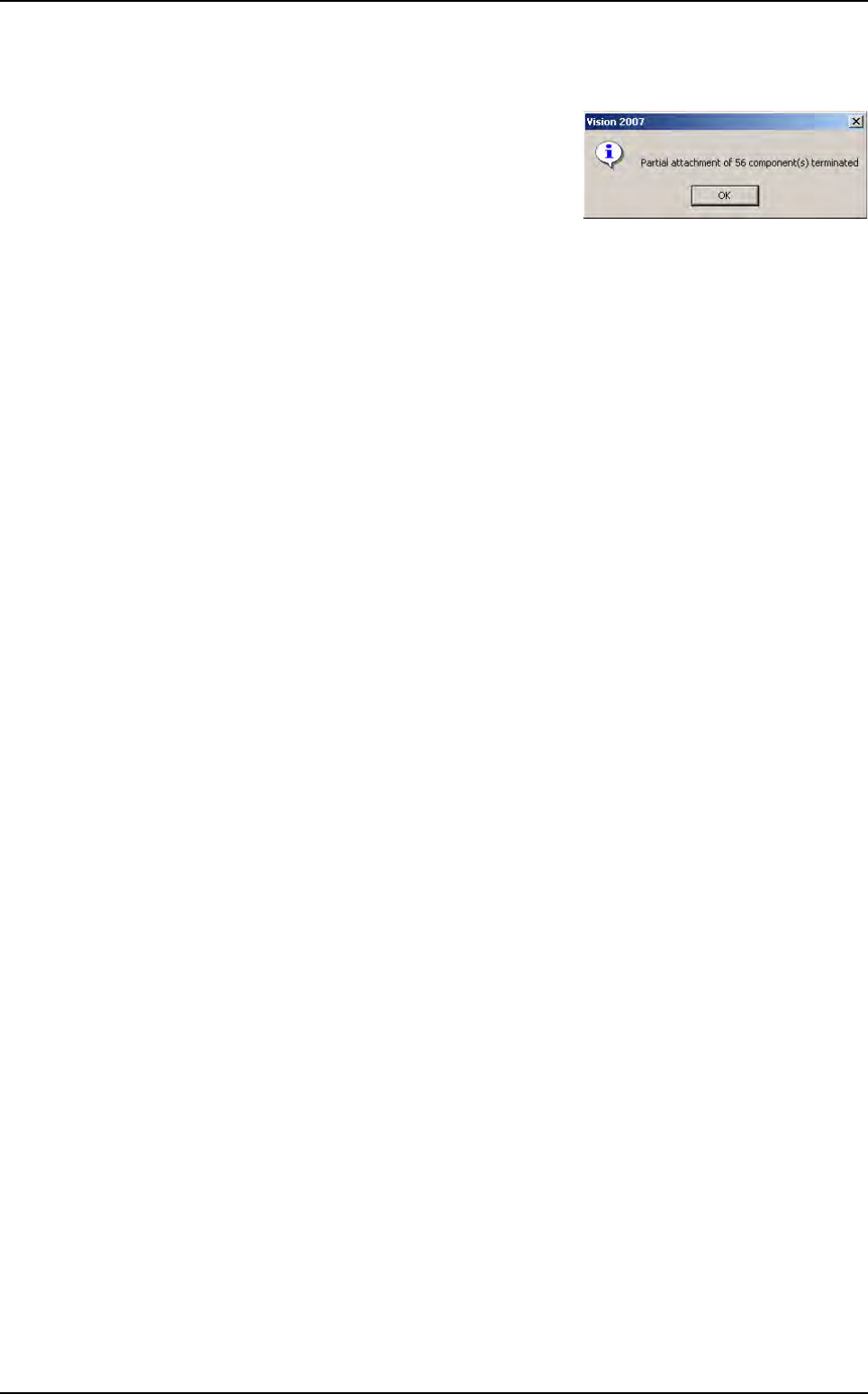
Case 5: the component is not defined in the zone file or the zone file is empty. The zone
edition window is displayed. Adjust the light settings.
Click on OK to validate your settings, the zones file
is updated with the new Jedec name and its re-
quired light adjustments. An information message
will appear confirming the re-attachement of the
components.
Second step if needed
Propagate these settings to the other components of the same Jedec.
1. Go to the pulldown menu Edit\Board\Create Joker zones to open a dialog box that
displays the content of the zone.dsc file. It then show the list of all jedec which have
already been configured with a joker zone.
2. Check the corresponding check boxes for the jedec you want to add joker zones.
Zones creation