VI User Manual.pdf - 第111页
.TST file edition Vision 2007 4.10 User Manua l Rev 01 5 - 3 5.2 Fiducials edition The fiducials are edited once the .tst file has been created. The fiducials of the boards to b e inspected can be panel, board, o r panel…
.TST file edition
5 - 2 Vision 2007 4.10 User Manual Rev 01
5.1.3 Mirror transformation
In Transformation menu, you can choose also mirror to rotate the .tst file with an horizontal or
vertical axis.
5.1.4 Change orientation
From the menu Edit / Transformation / Change orientation, the user can define the conveyor
flow direction used (Right Left or Left Right).
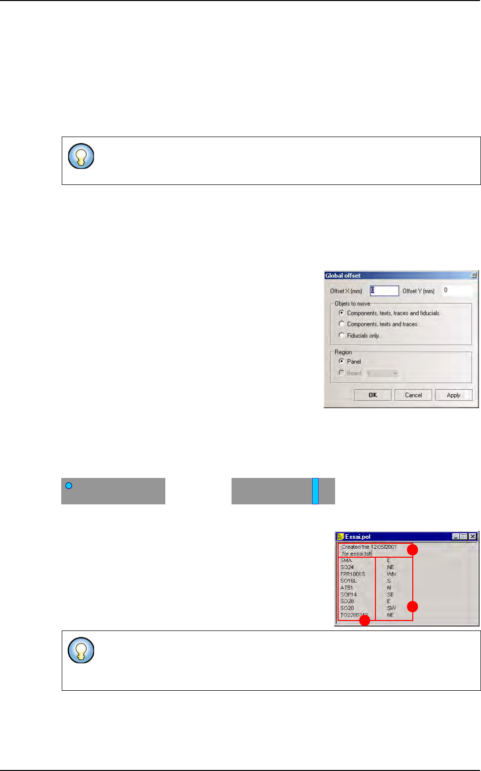
5.1.5 Global offset
This functionality allows applying a defined offset value on fiducials only, on components, text
and trace objects, or on all of them.
This offset can be applied to the whole panel or to one particular board.
The Global offset window is available from menu Edit /
Transformation / Global offset.
5.1.6 Polarity display
To see the components polarity mark on the repair station, configure them in the .tst file. 2 types
of polarity marks can be imported:
in a corner or on one side of the component
Indicate the position of the polarity for each Part Number, in a text file and import it in the .tst file.
To import a .tst file, create a text file, with any name but with
the extension .pol, that contains:
A The comment lines begin by ; (only for .pol files)
B Part_Number
C Its polarity location
Open your .tst file and in the menu Test file go to Import sub menu and select Polarity file. You
will see the polarity marks on the components. If you select no file, you will lose the previous po-
larity marks. If your .pol file has syntactic errors, a .log file will be created containing the error
message.
On a right to left machine: the reference is the bottom left hand corner of the board.
On a left to right machine: the reference is the bottom right hand corner of the board.
To indicate the polarity location, use: N for North, S for South, E for East, W for West.
Using 1 letter will generate a linear polarity and a combination of 2 letters will generate
a circular polarity in a corner.
A
B
C
.TST file transformation
.TST file edition
Vision 2007 4.10 User Manual Rev 01 5 - 3
5.2 Fiducials edition
The fiducials are edited once the .tst file has
been created.
The fiducials of the boards to be inspected can
be panel, board, or panel and board fiducials.
This is defined beforehand in the .vis file.
Click on any of the fiducial references. By de-
fault, they are yellow.
5.2.1 Edit fiducials window
The Edit Fiducials window is
activated by clicking on any of
the fiducials present in the .tst
file.
All the fiducial parameters are
accessible from this window.
Description (A) section:
By default: name of the fiducial.
P: panel or global fiducial,
C: board or local fiducial
Fiducial reading index:
The first is used for positioning.
The second for calculating readjustment.
The fiducial coordinates are extracted from the CAD data of the .vis file used to generate the .tst file.
Lighting (B) section:
Click and move the cursors to modify the brightness of your various lighting types in order to ob-
tain the best possible image.
It is very important that fiducials are
properly lit
.
Vision 2007 only uses 2 fiducials to
realign components.
The fiducial type is use-
ful if you program a
model in the library. It
won’t change the re-
alignement type.
This lighting is specific to fiducials: it is used during board inspection.
A
B
C
.TST file edition
5 - 4 Vision 2007 4.10 User Manual Rev 01
Window (C) section:
We must define a search area to find the fiducial.
These parameters form the search window around the CAD coordinates of the fiducial, defining
the zone in which Vision 2007 will locate the fiducial. If the fiducials are not located in the fiducial
search window, an error message will appear.
All the dimensions are in µm.
5.2.2 Fiducial inspection
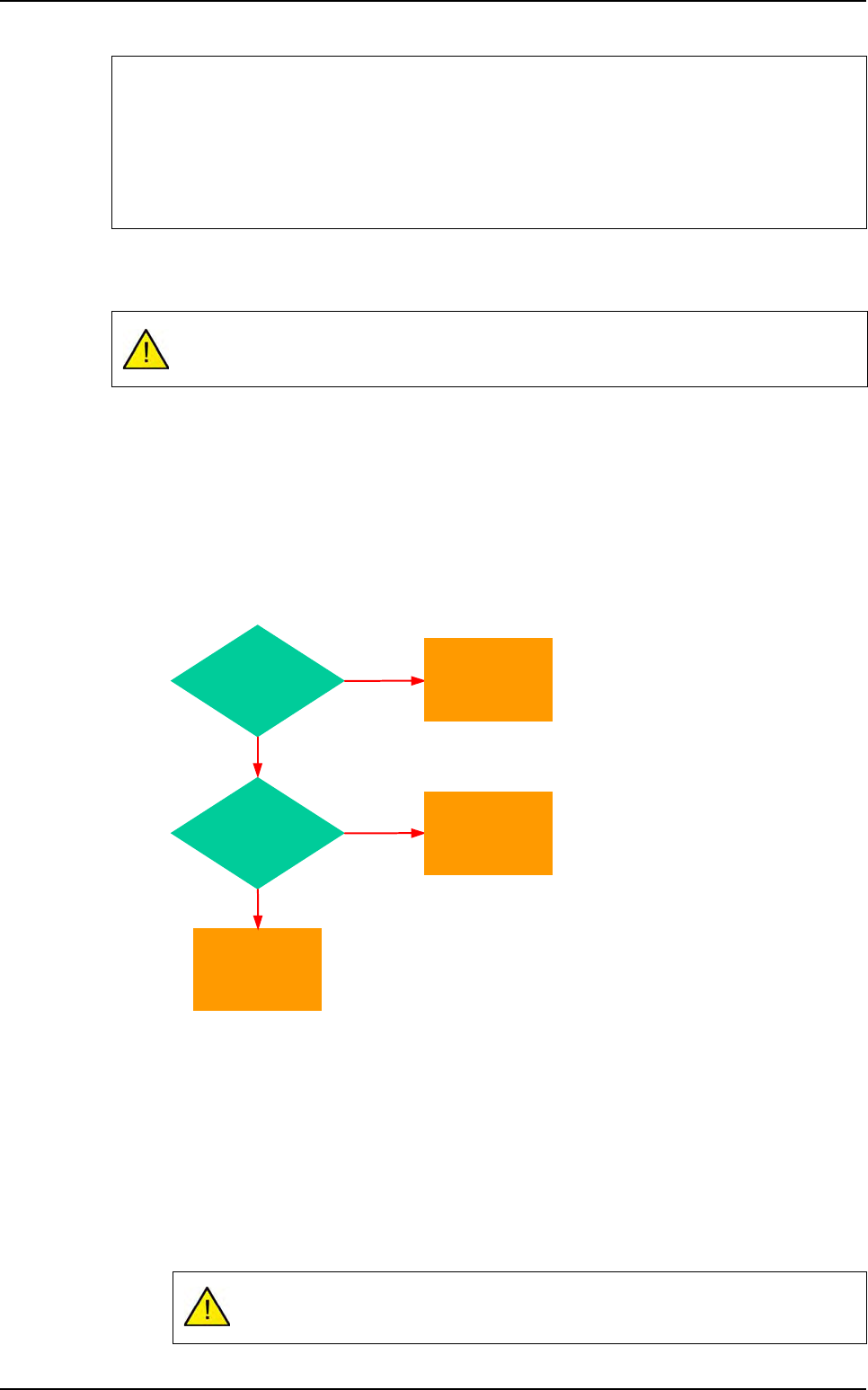
5.2.2.1 Priority order for fiducial inspection
5.2.2.2 Fiducial finder tool
Fiducial finder is the easiest fiducial tool to use if the fiducial is round and full. It is based
on the Vi-Pro treatment. To program the Fiducial finder, enter the Processing type and
the Diameter.
Definition of the fiducial type:
LIGHT (white circle on a black background),
DARK (black circle on a white background).
Fiducial diameter (in µm) only for circle fiducials.
Adjusting fiducial lighting
You must always adjust fiducial lighting to have the best possible image.
Move the camera above the fiducial until you can see the image of the fiducial when you adjust
its lighting.
Adjust the fiducial lighting to obtain a contrasted image of the fiducial.
The search window is defined in the PatMax parameters if you use a model in the library
to find a fiducial.
Available only for circular fiducials !
Yes
Library model
exists ?
No
Fiducial finder
configured ?
Yes
No
Use
Blob tool
parameters
Use
fiducial finder
Use
Library model
Fiducials edition