VI User Manual.pdf - 第118页
.TST file edition 5 - 10 Vision 2007 4.10 User Manual Re v 01 5.4.2.2 Level ta b To check each of the 5 levels, click on th e relevant tab. In this ca se, the parameters of lighting leve l 4 are acce ssible. Click on eac…
.TST file edition
Vision 2007 4.10 User Manual Rev 01 5 - 9
5.4 Zones edition
Zone size depends on the pixel size and the number of pixels of the camera. The specifications for the
zone dimensions, defined on calibration, are found in the Vision parameters menu accessible from
the Maintenance Mode.
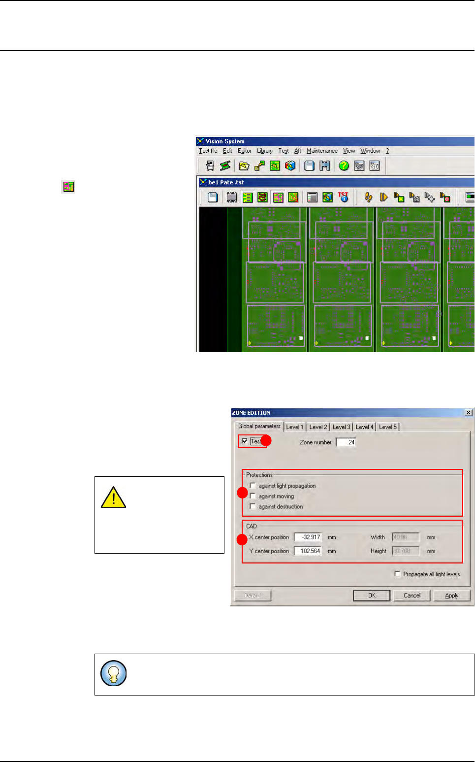
5.4.1 Viewing and placing zones
Select Display zones in the
Image menu to bring up all
the inspection zones, or click
on the Display zones icon
in the tool bar of the .tst
file window.
Using the component CAD
data in the .vis file and the
component dimensions, Vi-
sion 2007 automatically plac-
es the inspection zones and
allocates all the components
to zones.
5.4.2 Zone edition window
5.4.2.1 Global Parameters tab
Click on a zone to bring up the
Zone edtion window.
The Global Parameters are
valid only for the selected
zone.
Tick Test (A) to inspect the
zone.
In Protections (B) area, tick
the types of protection for the
selected zone.
In CAD (C) area, change the centre coordinates and size the to modify the zone.
If you manually mod-
ify zone position,
you have to reaffect
all components to
zones.
When you propagate parameters from another zone, protected zones appear
in blue in the .tst file.
A
B
C
.TST file edition
5 - 10 Vision 2007 4.10 User Manual Rev 01
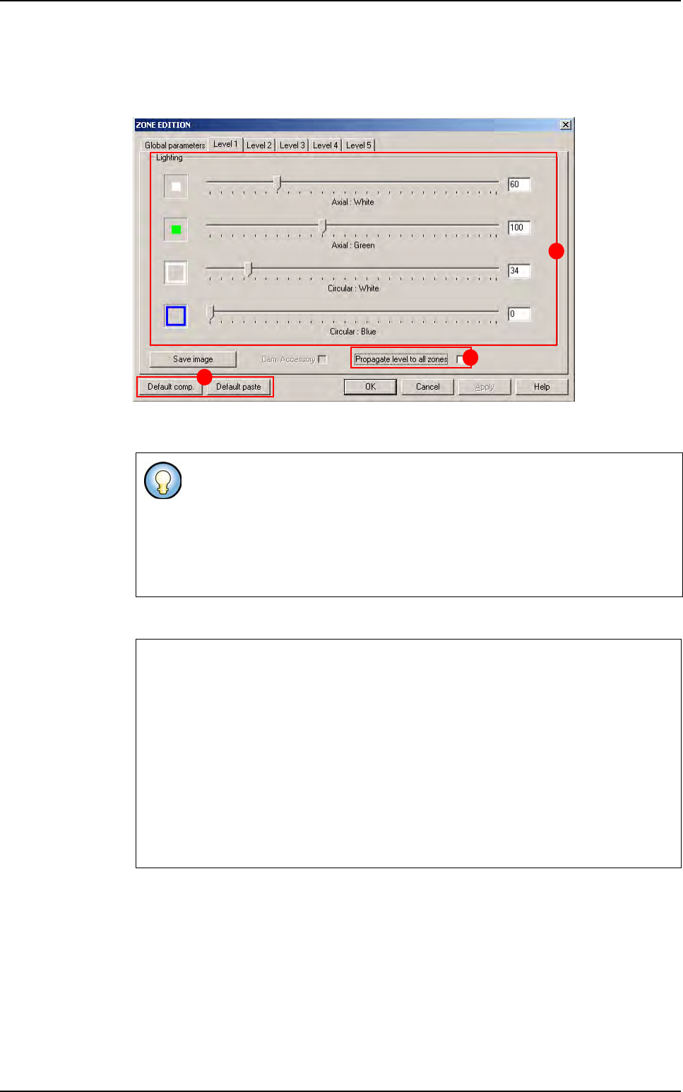
5.4.2.2 Level tab
To check each of the 5 levels, click on the relevant tab. In this case, the parameters of
lighting level 4 are accessible.
Click on each cursor (A) and slide it to the required value in order to adjust the lighting
levels.
Tick Propagate level to all zones (B) to copy the level lighting adjustments to all zones.
Click on the Default comp./paste buttons (C) to reset the lightings to their default values,
for both pads and components.
If you already know the value that you want to enter, you can enter it directly in
the text fields.
You can also use the left and right arrow keys on the keyboard to move the cursor
and change the value in the text field in steps of 1.
The page skip keys to change in steps of 50. The corresponding lighting is visible in
the camera window.
Propagation of lighting level adjustments
Each of the 4 different lighting types extend between 1 and 255.
We recommend that all the zones of the .tst file have the same lighting adjustments.
In fact, in the library, each component type is linked to a lighting level (1 to 5) that
must be the same for all.
If you change the adjustments of a lighting level and propagate it to all the zones, all
the components with this lighting level will be affected by these changes. For this
reason, you must make sure that the selected lighting level is suitable for all the
components.
There are more than 255 x 255 x 255 x 255 possible lighting combinations.
A
B
C
Zones edition
.TST file edition
Vision 2007 4.10 User Manual Rev 01 5 - 11
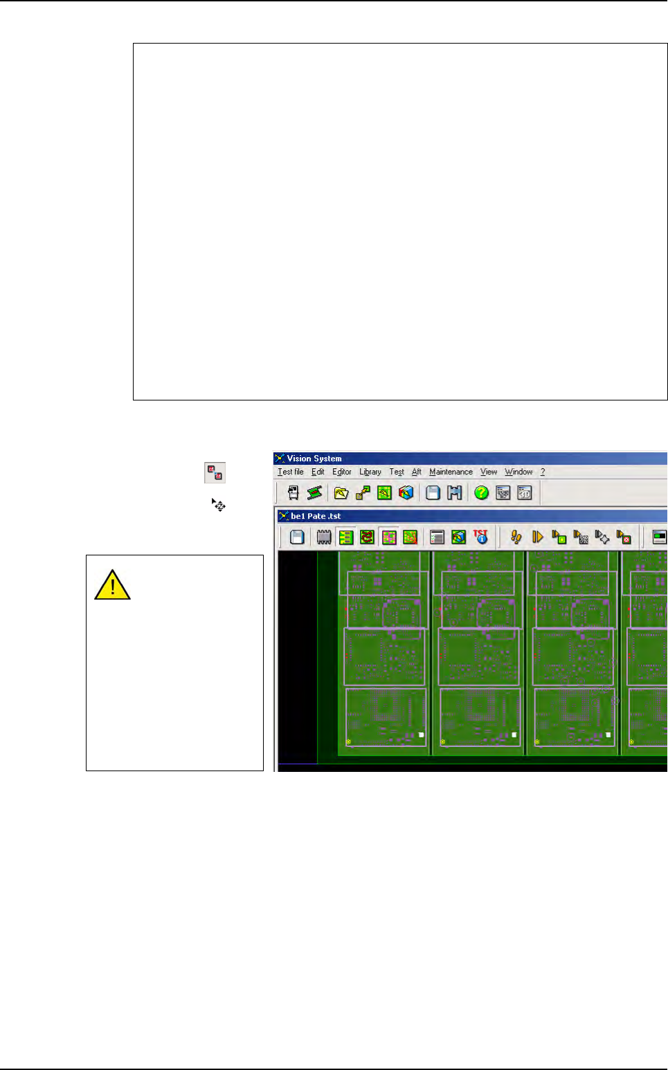
5.4.3 Moving zones
To move a zone, click on
Move zone button in the
Tools palette, the mouse
cursor change to , and
with a mouse click, select
and move the wanted zone.
Reset to default values
The reset to default values is available by clicking on the Default comp. or Default
paste buttons from the Zone Edition window.
The default lighting values for components and pads are defined for each zone in the
defaultvalue.ini file:
[Lighting zone 1]
Direct Amber(1,255)=70
Direct green(1,255)=0
Horizontal amber(1,255)=0
Horizontal green(1,255)=0
Camera accessory(0,1)=0
[Lighting zone 1 (paste inspection)]
Direct Amber(1,255)=70
Direct green(1,255)=0
Horizontal amber(1,255)=0
Horizontal green(1,255)=0
Camera accessory(0,1)=0
Check that the com-
ponents linked to
the zone are still in
the zone, after mov-
ing a zone.
When you click on a
zone with the right
mouse button, the
color of the zone
changes from ma-
genta to yellow.
Zones edition