VI User Manual.pdf - 第125页
.TST file edition Vision 2007 4.10 User Manua l Rev 01 5 - 17 5.7 Connectors edition 5.7.1 Connector sub menu To edit connec tor, go in Edit menu and select Connector sub menu : 1. Select Add connector... to run a wizard…
.TST file edition
5 - 16 Vision 2007 4.10 User Manual Rev 01
5.6 Treatments selection
You have the possibility to run or not some functionalities for each model. For one .tst file you can de-
select some tests for components or some labels for text inspection (OCV). The configuration is saved
in the .tst file. When you start production, we execute only the selected tests. When you deselect op-
tions, it does not change the library:
The corresponding treatment is not executed,
The corresponding image is not acquired.
5.6.1 For components
In Edit menu, go to
Component and press
Select functionality.
This will display the list of
all the models you have
in the .tst file.
By default, all the func-
tionalities are ticked. (It
does not check what is
programmed in the li-
brary)
You can deselect some
tests by removing the
cross of the corresponding column (You can not remove the Presence Test).
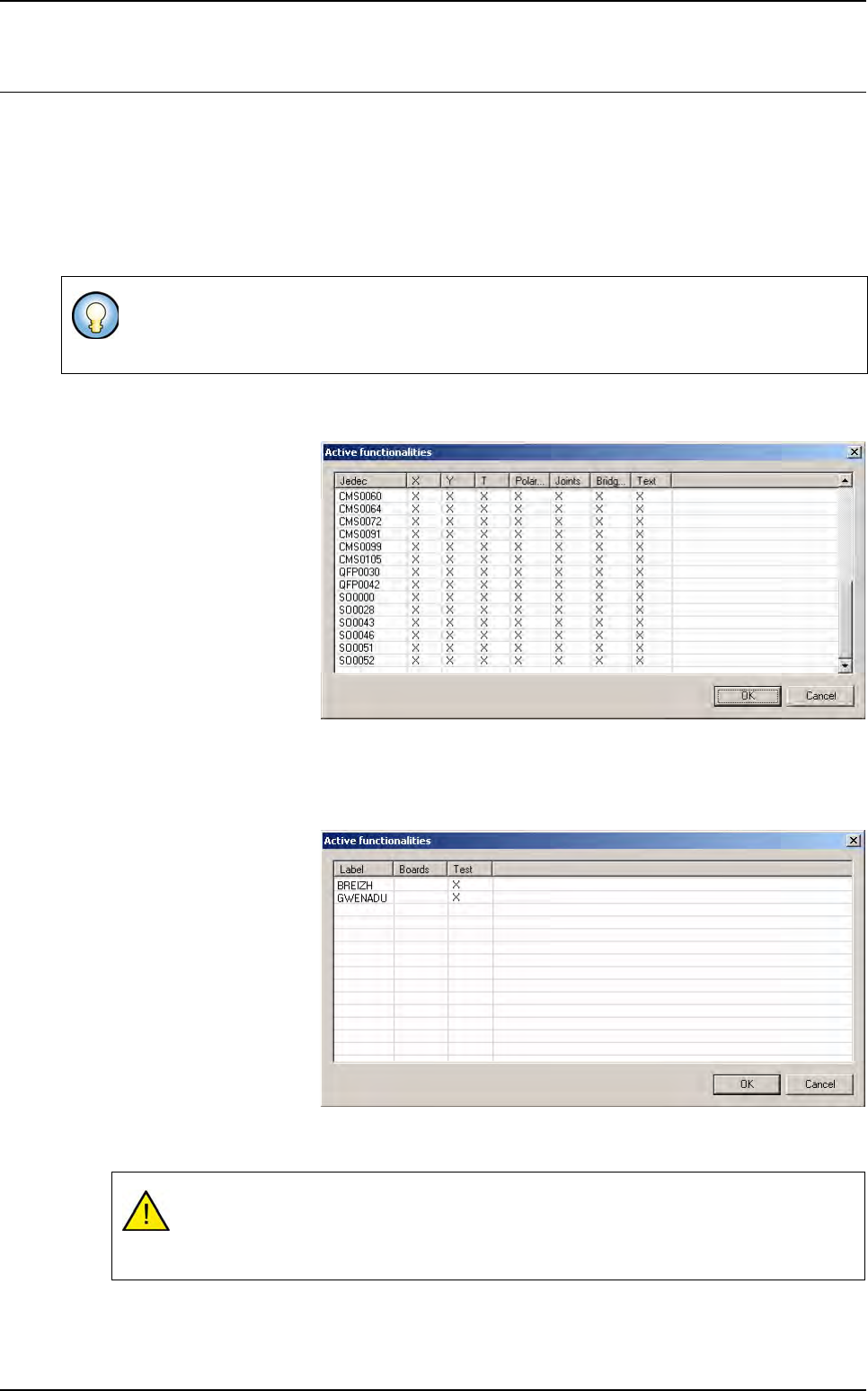
5.6.2 For text
In Edit menu, go to Text
and press Select labels.
This will display the list of
all the labels you have in
the .tst file.
By default, the text in-
spection is ticked. If you
click on the top of the col-
umn you will remove /
add the test for all the
models. If you click on
the top of the column you
will remove the text veri-
fication for the whole panel. You can deselect some labels by removing the cross of the corre-
sponding line.
This tool is helpful when you use a library made for post-reflow inspection and you want to use
it pre-reflow. You just have to deselect the joints and brigdes tests without changing anything
in the library. You still can use the same library pre and post-reflow.
Removing a text verification revises automatically the Test text box from the Text object
edition window.
Removing a text label, changes automatically the links organization.
.TST file edition
Vision 2007 4.10 User Manual Rev 01 5 - 17
5.7 Connectors edition
5.7.1 Connector sub menu
To edit connector, go in Edit menu and select Connector sub menu:
1. Select Add connector... to run a wizard to add a connector.
2. Select Edit connector group... to open the connector group editor.
3. Select Export a connector library... to create a connector library based on connector in the
.tst file.
4. Select Import a connector library... to convert all component which have the same name as
connector model to a connector.
5. Select Test connectors to do connector test.
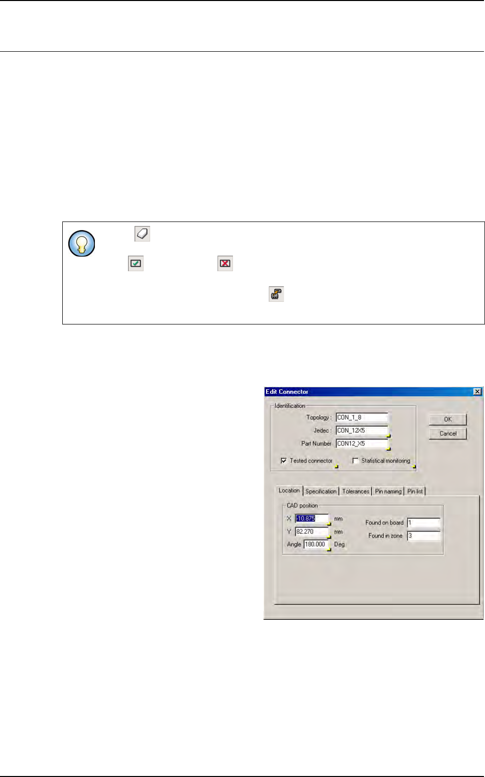
5.7.2 Connector edition box
5.7.2.1 Location tab
These parameters define the con-
nector CAD position in the .tst file.
If Erase icon is pushed in, you can directly remove component using mouse without
answer to the fatal question Are you sure you want to remove this component.
If Test icon (or No test icon) is pushed in, you can directly put in test or remove
from test component with the mouse.
If Convert component to connector icon is pushed in, you can choose with the
mouse, which component you want to convert to connector.
.TST file edition
5 - 18 Vision 2007 4.10 User Manual Rev 01
5.7.2.2 Specification tab
This tab shows the connector features.
In Connector (A) section, the Size X
& Y is the connector size in X, Y direc-
tion.
Press Auto calculate pins specifica-
tion (B) button to calculate automati-
cally connector feature according to
pin which are under the connector. If
you have not pin in your .tst file, you
can enter manually connector features
and the connector wizard could create pin component according to connector specifica-
tion.
In Connector’s pins (C) section:
Nb pin X & Y: number of pin in the connector in the X, Y direction.
Step X & Y: step, in X, Y direction, between 2 pins.
Offset X & Y: offset apply to the pin matrix from connector center position in X, Y direc-
tion.
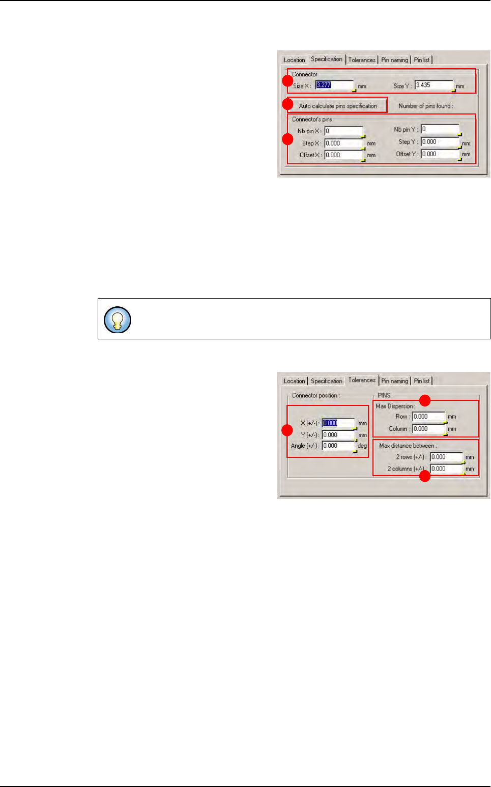
5.7.2.3 Tolerance tab
This tab show the connector toleranc-
es and pin alignment tolerances
In Connector position (A) section:
X & Y (+/-): maximum distance be-
tween connector CAD and real posi-
tion in X, Y direction.
Angle (+/-): maximum angle between
connector CAD and real angle.
In Pins section:
Maximum dispersion (B):
Row: maximum distance between 2 pins of the same row in Y direction.
Column: maximum distance between 2 pins of the same column in X direction.
Maximum distance between (C):
2 rows (+/-): maximum distance between rows CAD and real step.
2 columns (+/-): maximum distance between columns CAD and real step.
All this specifications are given for a connector at 0°.
B
A
C
B
C
A
Connectors edition