VI User Manual.pdf - 第129页
.TST file edition Vision 2007 4.10 User Manua l Rev 01 5 - 21 5.7.6 Results 5.7.6.1 Alignment resu lt At the end of the continuous run, we compute the disper- sion using all pin position. So the software change all pin r…
.TST file edition
5 - 20 Vision 2007 4.10 User Manual Rev 01
5.7.3 Connector result
Connector results are computed when all pins have been controlled. There are orange icon for
connector error:
Missing connector ,
Position error ,
Soldering error ,
Polarity error ,
Pin missing error ,
Pin alignment error ,
Column or line step error .
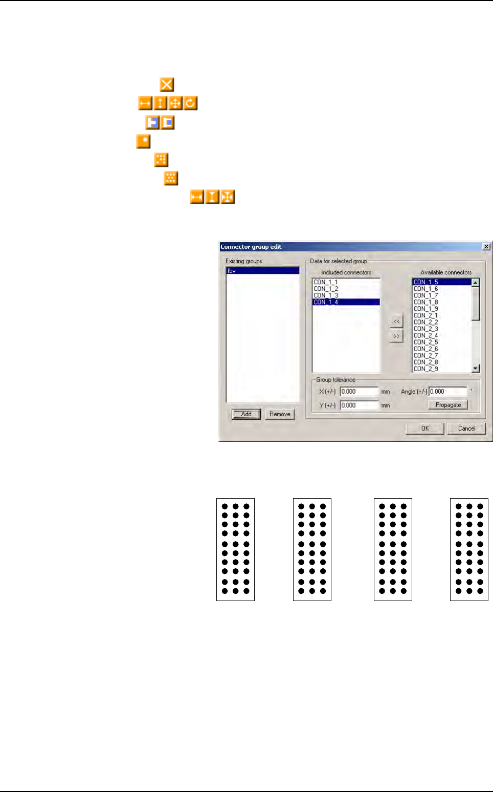
5.7.4 Connector group edition box
The connector group tool allows
to control alignment between
connector. This window shows
existing groups and their fea-
tures.
Thanks to the backplane inspec-
tion we can control components,
pin tip and pin through hole with
the same acquisition system.
5.7.5 Pin name
Currently, the pins are creat-
ing by importing a Gerber
file. Pins are linked to their
connector but they are
named in random way.
Z A B
27 30
1
10
1
1
0
10 30
1 3 1 21
Connectors edition
.TST file edition
Vision 2007 4.10 User Manual Rev 01 5 - 21
5.7.6 Results
5.7.6.1 Alignment result
At the end of the continuous run, we compute the disper-
sion using all pin position. So the software change all pin
result considering the alignment result. If a pin is not align
it will be in position error, otherwise it will ok without take
care of the CAD position.
We can disable the connector computation so we can still
have the pin position from CAD position.
5.7.6.2 Step result
This result will be compute at this end of the board inspec-
tion. 2 new kinds of error are created for pin and connec-
tor: Row step and Column step with new icon error.
In the continuous mode run, all pin are checked and re-
turn their position from the CAD position. At the end of the
board inspection, all pin results are corrected considering
columns and rows step.
This computation could be optional.
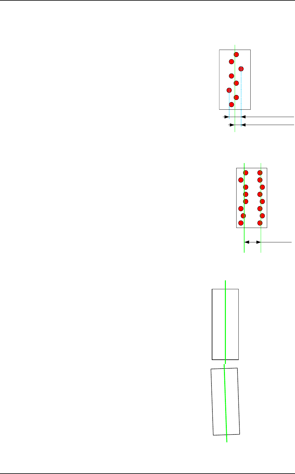
5.7.6.3 Connector to connector alignment
The first result return for the connector will come from
the library model. At the end of the continuous run
mode, using the pin position, we will compute the linear
regression line of the connector.
So we will know if connector from the same group are
really aligned. Considering this result, we will change
the connector result as a position error if it is misalign.
The connector will also have:
A pin alignment error if a pin is misalign in a row or
column.
A pin missing if one or several pins are missing.
Column
mean value
Column dispersion
X Pin position
Column step
Column 1
mean value
Column 2
mean value
Connector
2
linear regression line
Connector 1
linear regression line
Connectors edition
.TST file edition
5 - 22 Vision 2007 4.10 User Manual Rev 01
5.8 Test coverage report
5.8.1 Presentation
The test coverage report allows to know at a glance which tests (polarity, presence, etc…) will
be performed on each element inspected. The user has just to click on icon to know this. These
informations are easy to print and to export in order to be opened with Excel or reopened with
Vision 2007.
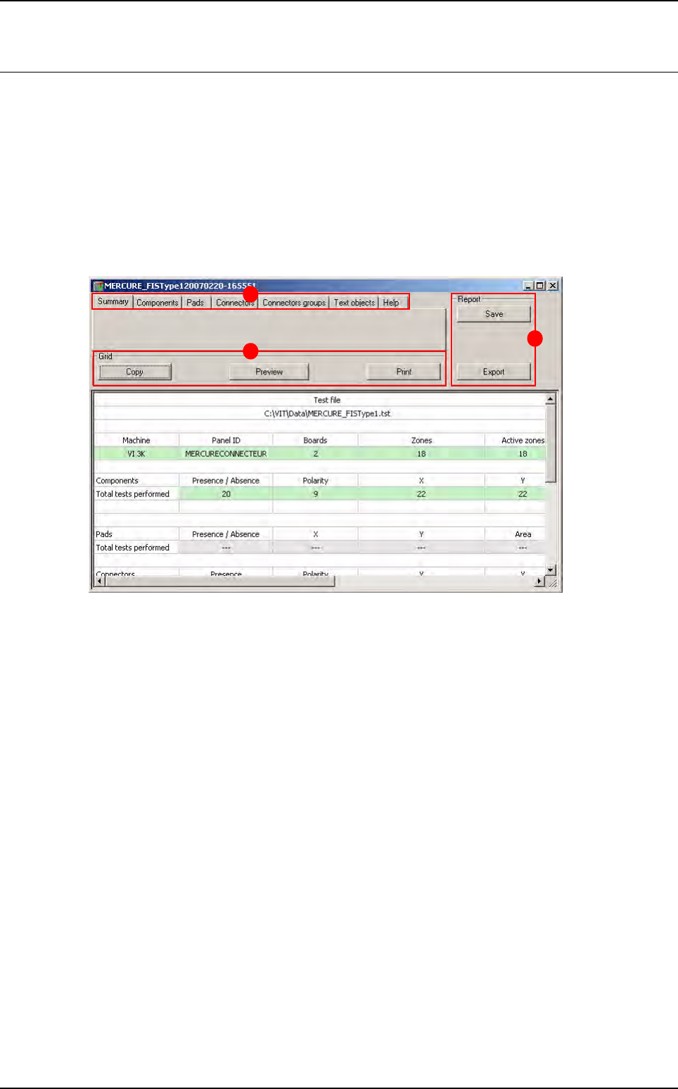
5.8.2 Test coverage report description
When opening the test coverage report, the window below appears.
This window is divided in 3 main parts:
The Menu (A) section
• Summary tab
• Report tabs
The Grid (B) section
The Report (C) section
A
B
C