VI User Manual.pdf - 第146页
Match Maker 6 - 12 Vision 2007 4.10 User Manu al Rev 01 6.4.3.2 Reference designa tor selection This combo di splays the list of the reference designators related to the current Part Number. While a reference is selected…
Match Maker
Vision 2007 4.10 User Manual Rev 01 6 - 11
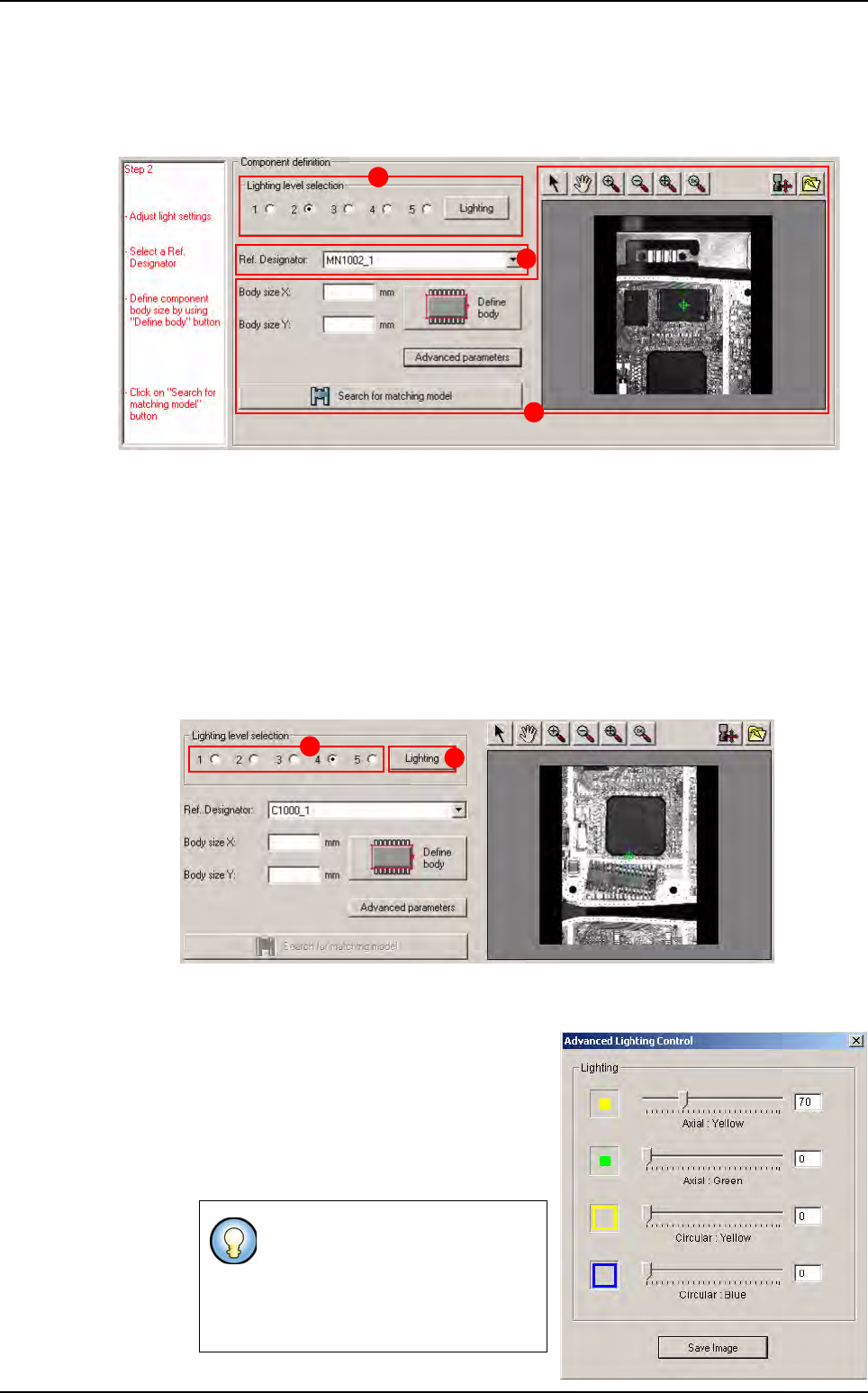
6.4.3 Step 2: Component definition
This second step enables to define the geometry of the component by using the image of the
camera. Several steps are necessary:
Lighting level selection (A): to define geometry of the unknown component, adjust lighting in
order to observe the shape of the component correctly.
Reference Designator selection (B): to select an image where the user observes the shape
of the component correctly to help him in the definition of the body.
Component Body size definition (C): to define the geometry of the component. Search for
matching model.
6.4.3.1 Lighting level selection
2 types of lighting can be chosen:
Standard lighting (A): lighting defined by default (1 to 5), located in a default.ini file.
Select a lighting level, then the picture is refreshed with the lighting level.
Specific lighting: lighting with axial and cir-
cular adjustments of intensity. Click on the
Lighting button (B). The
Advanced Light-
ing Control
window appears.
Set the lightings and close the window, then
the picture is refreshed and the radio but-
tons are all empty.
In the
Advanced Lighting Control
window, it is possible to save the
image of the component with this
specific lighting by clicking on
Save Image. It is useful for re-use
on offline station.
A
B
C
A
B
Match Maker graphical user interface
Match Maker
6 - 12 Vision 2007 4.10 User Manual Rev 01
6.4.3.2 Reference designator selection
This combo displays the list of the reference designators related to the current Part Number.
While a reference is selected, the camera moves to the selected component on the panel.
1. A Reference Designator is selected, the component appears to the screen.
2. Select a new Reference Designator, the camera moves towards the new component.
6.4.3.3 Component body size definition - Search for matching model
The component body size definition is composed of:
Body size fields (A), two cases:
Family without leads Family with leads
Board 1
Board 4
A
B
D
C
E
Match Maker graphical user interface
Match Maker
Vision 2007 4.10 User Manual Rev 01 6 - 13
Define Body button (B). Define the component body without the leads using a magenta
square located in the camera window.
The
Camera window
(
C
)
is composed of a
screen and a toolbar at the top which enables to
define the contour of the component precisely:
Select
Move
Zoom in
Zoom out
Fit image
Zoom 100%
Move camera
For offline station user (Save as)
Advanced parameters button (D) (optional). Set others parameters in order to optimize
the research.
Search for matching model button (E). Enable to find a list of model matching the un-
known component.
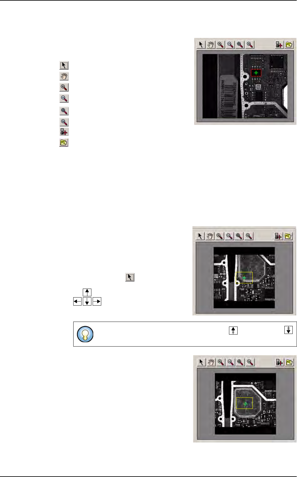
The component body size definition requires a logical sequence of actions described be-
low
and that depend of the situation: dimensions of the component known or unknown.
Case 1: the dimensions of the component are known
1. Check the position of the component in the
camera, it depends on the result of the execu-
tion of the fiducials:
If the
execution of fiducials fails,
the camera
is not centered on the component. The
component is far away from the center then
click on the button , the camera moves
with the keyboard arrows of your computer:
If the execution of fiducials is OK,
the cam-
era is centered on the component. In the
toolbar, all the buttons are activated.
Motion steps can be increased with the page up and page down
keys.
Match Maker graphical user interface