VI User Manual.pdf - 第151页
Match Maker Vision 2007 4.10 User Manua l Rev 01 6 - 17 In Encompassing area X/Y (B) define the length and the width of the component with the leads. Click on Define area button (C) to define the co mponent body with the…
Match Maker
6 - 16 Vision 2007 4.10 User Manual Rev 01
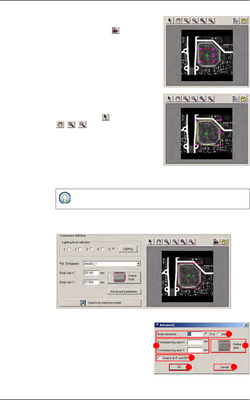
2. A magenta square appears in the center of the
screen. In the toolbar, all the buttons are acti-
vated except the button .
3. Resize the magenta square and surround the
body of the component correctly (do not in-
clude leads).
Click on the button provided, the buttons
, , were not selected before.
If not, the pointer mouse enables to move the
enchorage points of the contour.
4. Click on the Define Body button. Match Maker loads the capture (the square be-
comes red) and the Body size values: X,Y appear in the fields.
In the toolbar, all the buttons are activated. The Advanced parameters and the
Search for matching model buttons are activated.
5. Click on the Advanced parameters but-
ton. A Advanced window appears (the
Model selection table (Step 3) and
Search for matching model button are
not activated).
The Body tolerance (A) indicates by de-
fault 10 %, it is possible to modify this val-
ue. This tolerance is given for body size
X and body size Y.
The Nb of leads is not filled automatically, the user must enter the value.
C
F
E
A
D
B
Match Maker graphical user interface
Match Maker
Vision 2007 4.10 User Manual Rev 01 6 - 17
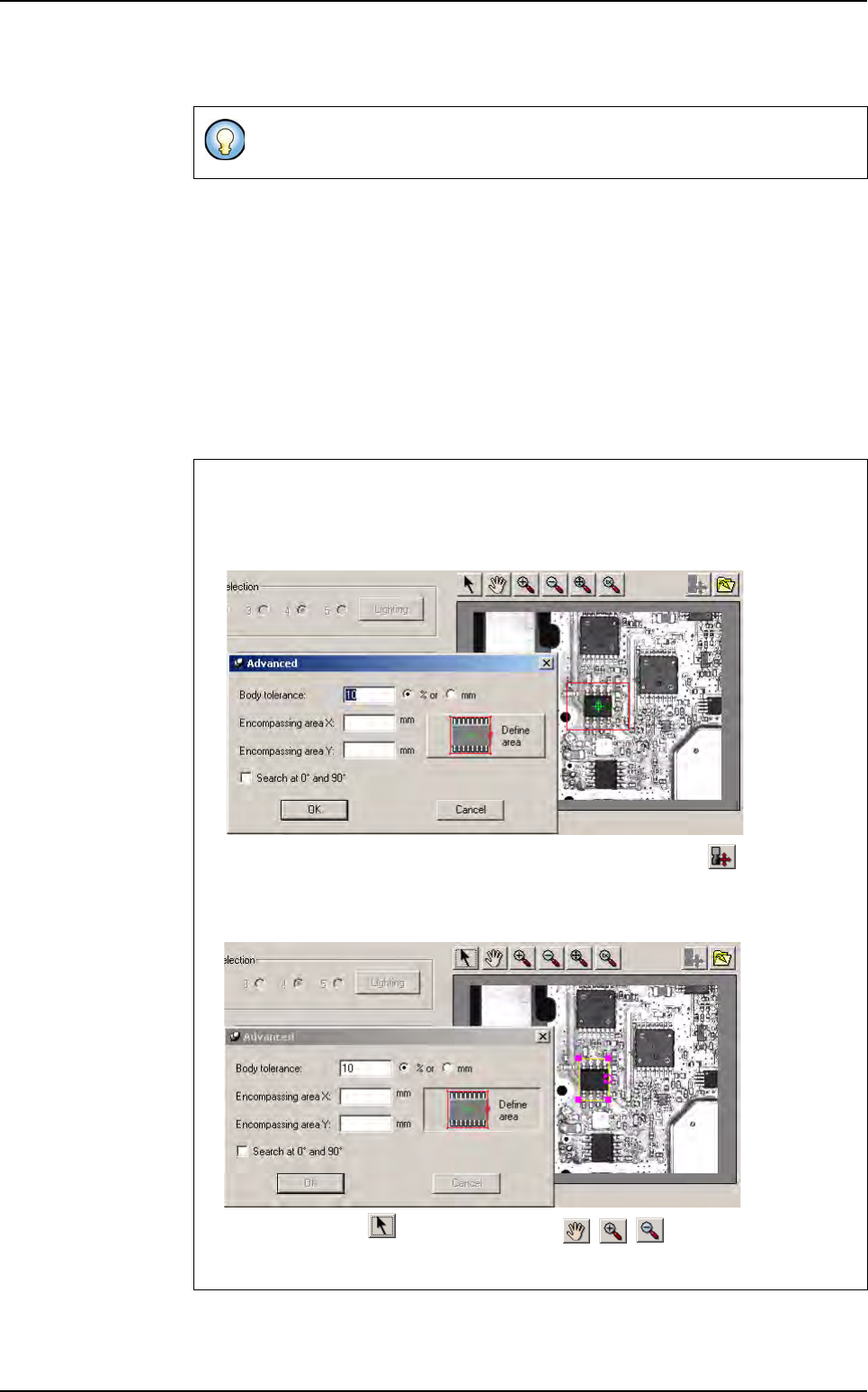
In Encompassing area X/Y (B) define the length and the width of the component with
the leads.
Click on Define area button (C) to define the component body with the leads using a
magenta square located in the camera window.
It is possible to tick Search at 0° and 90° (D): Match Maker search a component in
the two positions (certain types of components are recorded with an angle different of
the component on the board).
The OK button (E) is always activated (except when the Define Area button is select-
ed). When the user clicks on, the filled fields are saved and the Step 3: Model selec-
tion can be followed.
The Cancel button (F) is always actived. When the user clicks on, the filled fields are
not saved and the Step 3: Model selection can be followed.
If the dimensions of the component are known then the user can enter the
fields and click on the OK button.
Component body size definition with leads
1. Click on the Define area button. A magenta square appears in the center of the
screen.
In the toolbar, all the buttons are activated except the button .
2.
Resize the magenta square and surround the body with the leads of the compo-
nent correctly.
Click on the button provided, the buttons , , were not selected before.
If not, the pointer mouse enables to move the enchorage points of the contour.
Match Maker graphical user interface
Match Maker
6 - 18 Vision 2007 4.10 User Manual Rev 01
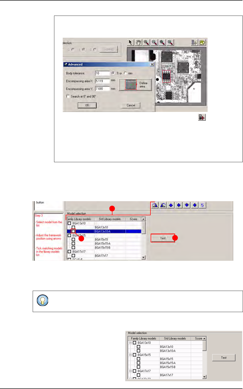
6.4.4 Step 3: Model selection
This third step enables to choose a model which matches to the «unknown» component. Sev-
eral steps are necessary:
A Test
B Preselect a model and adjust the framework to the component
C Select a model or a family model
6.4.4.1 Test
A Test button enables to launch a
test on each model. Before click
on Test button, the column score
is empty.
3. Click on the Define area button. Match Maker loads the capture (the square be-
comes red) and the Encompassing area values: X,Y appear in the fields.
In the toolbar, all the buttons are activated except the button .
When the body size is defined, the Step 3 is activated (Step 2: black, Step 3:
red) and at this moment the Step 3 can be followed.
4. Click on the OK button. The filled fields are saved and the window closes. The
Advanced parameters and the Search for matching model buttons become
ative. The Model selection table (Step 3) also is activated.
At this step, the user can return to the step 1 and 2 if the result of the search is not correct
(see §
6.4.2 Step 1: Package type selection
, §
6.4.3 Step 2: Component definition
).
C
B
A
Match Maker graphical user interface