VI User Manual.pdf - 第153页
Match Maker Vision 2007 4.10 User Manua l Rev 01 6 - 19 After click on Test button, the test is launched and e nables to make the decision correspond s best. The result of the test (in percent: 0 to 100%) appears in the …
Match Maker
6 - 18 Vision 2007 4.10 User Manual Rev 01
6.4.4 Step 3: Model selection
This third step enables to choose a model which matches to the «unknown» component. Sev-
eral steps are necessary:
A Test
B Preselect a model and adjust the framework to the component
C Select a model or a family model
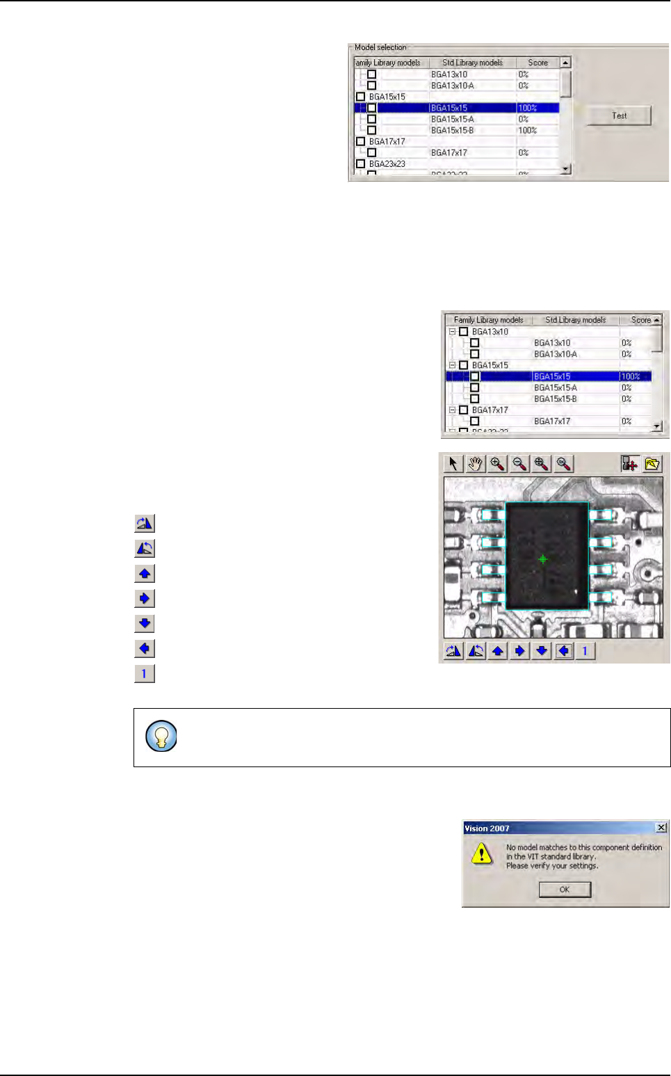
6.4.4.1 Test
A Test button enables to launch a
test on each model. Before click
on Test button, the column score
is empty.
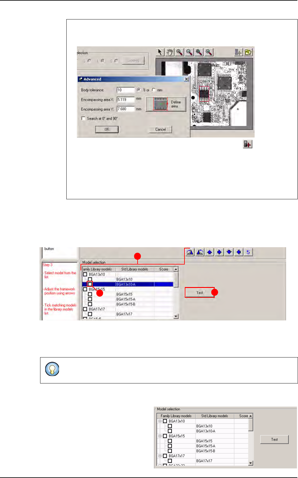
3. Click on the Define area button. Match Maker loads the capture (the square be-
comes red) and the Encompassing area values: X,Y appear in the fields.
In the toolbar, all the buttons are activated except the button .
When the body size is defined, the Step 3 is activated (Step 2: black, Step 3:
red) and at this moment the Step 3 can be followed.
4. Click on the OK button. The filled fields are saved and the window closes. The
Advanced parameters and the Search for matching model buttons become
ative. The Model selection table (Step 3) also is activated.
At this step, the user can return to the step 1 and 2 if the result of the search is not correct
(see §
6.4.2 Step 1: Package type selection
, §
6.4.3 Step 2: Component definition
).
C
B
A
Match Maker graphical user interface
Match Maker
Vision 2007 4.10 User Manual Rev 01 6 - 19
After click on Test button, the test
is launched and enables to make
the decision corresponds best.
The result of the test (in percent:
0 to 100%) appears in the column
score for each model.
6.4.4.2 Preselect a model and adjust the framework to the component
After having clicked on Search for matching model button, the user sees the result in
the table (models displayed).
Several models are displayed
The user must click on only one line related to a
model.
The selected model line becomes blue.
A framework is displayed in the camera window.
After having chosen the model, seven buttons
appear under the camera window.
Model framework rotation + 90°
Model framework rotation - 90°
Move model framework up
Move model framework right
Move model framework down
Move model framework left
Step increment of the model framework mov-
ing (in pixel: 1, 5, 10).
Only one model is displayed
The user is prevented by a message
. The different
settings which must be verified in priority are:
Body size X
Body size Y
Nb of leads.
The others settings may be also verified.
When the settings are realized, click once more on the
Search for matching model
button.
The user can move the framework
in
order to surimpose and make sure it matches
the component.
Match Maker graphical user interface
Match Maker
6 - 20 Vision 2007 4.10 User Manual Rev 01
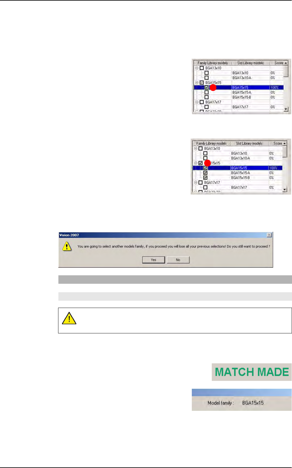
6.4.4.3 Select a model or a family model
The user can realize several actions:
Select a model
Tick the corresponding check box (A).
Select a family to optimize a future research
Tick the corresponding check box to the family (
B
).
Select a new model family when another is selected
A new window informs the user of the modification.
All these selections imply several modifications:
Step 1, 2, 3 become green (steps realized and validated)
The information: MATCH MADE appears on the right
table
The information: Model family appears in the
top part.
If you click on Then
Yes the new model is saved
No return to the preceding family
Only one family can be selected. By selecting another family, the previous
selection is lost.
A
B
Match Maker graphical user interface