VI User Manual.pdf - 第163页
Vision 2007 4.10 User Manua l Rev 01 7 - 1 Chapter 7 Tools library 7.1 Component library The component library is organized in 2 parts: A .bm file containing in formation on the component models. A directory of the s…
Match Maker
6 - 28 Vision 2007 4.10 User Manual Rev 01
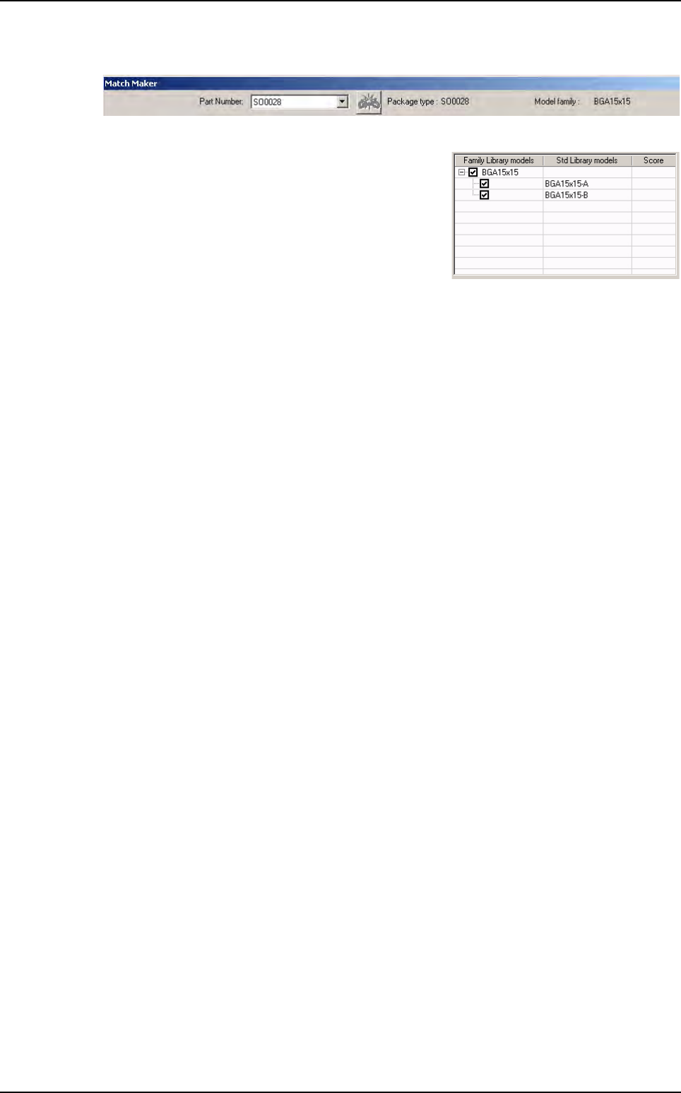
7. Launch Match Maker. Click on the Match Maker button. The Match Maker window appears:
Select the same Part Number.
8. In the table, the family BGA15x15 appears with the
models BGA15x15-A and BGA15x15-B.
9. After having clicked on the Next button, continue in the Wizard TST such as (see §6.5 Wizard
TST after use of Match Maker).
In the Customer library there are the Standard Library models:
BGA15x15
BGA15x15-A
BGA15x15-B.
Examples of link between Part Number and Library
Vision 2007 4.10 User Manual Rev 01 7 - 1
Chapter 7
Tools library
7.1 Component library
The component library is organized in 2 parts:
A .bm file containing information on the component models.
A directory of the same name containing the .cvl files.
The following information are general for each component model:
Component search window size.
Tolerances used for the inspection.
Tool(s) used for the inspection.
Link(s) between the different processing sequences.
Different lights used.
This chapter will teach you how to:
Create a table of images from a full and empty panel.
Create models in the library from the table of images.
Create synthetic images with BuildModel.
Create synthetic images with Image Edit.
7.1.1 Creating a table of images
7.1.1.1 Full panel
1. Run Vision 2007 software and open the .tst file corresponding to the panel that you
want to inspect. The conveyor will be adjusted automatically.
2. Click on the Load board icon or use the keyboard shortcut F3.
3. Click on the Fiducial execution icon to calculate panel readjustment. Check, and ad-
just if necessary, the intensity of the lighting.
To be able to use these different functions
You must have a .tst file corresponding to the panel that you want to inspect.
Fiducial treatment must be correctly defined to ensure proper board readjustment when the images of
the components are taken.
Place the panel with the components in the machine.
Ensure that the panel locks and board supports are properly adjusted.
Tools library
7 - 2 Vision 2007 4.10 User Manual Rev 01
4. In the Library menu, go to Create a table of images and select Full board. The Li-
brary Pictures window appears and then select the directory where the captured im-
ages are to be stored. If necessary, select or create a new folder. Click Open to
validate your choice and continue.
The machine is in the process of taking the images of the panel’s components. Each
component will be photographed 5 times, one image for each type of lighting predefined
in the zone with which the component is associated. These images are automatically
saved in the .bmp format in the previously defined directory.
7.1.1.2 Empty panel
The process for creating a table of images for an empty panel is the same as for a full
panel. It enables testing of the treatment operations on an empty panel. In Library menu,
go to Create a table of images and select Empty board.
7.1.2 Creating models from a table of images
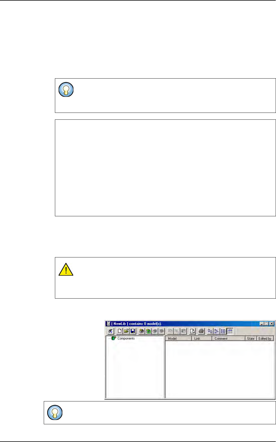
1. Select New Library in
the Library menu. A
New library window
appears.
2. Select Create models
from the current se-
ries in the Models
menu to create auto-
matically models in the
library from the table of
images.
If the video image window is active, you can see the component images
scrolled.
Creation of a table of images can take several minutes.
Size of the component image
The size of the components on the panel varies according to their type.
How does the machine know the size of the photograph window to enable image capture of
each component?
Vision 2007 takes the size of the components from the .tst file. In fact, each component is rep-
resented in the .tst file with a size taken from the library.
If, during creation of the .tst file, all components were not defined in the library, these component
were represented with a size: 0.5 x 0.5. So it is very important to have the best possible repre-
sentation of the board. This can explain why a photo of a component is too small.
To enable good image acquisition, Vision 2007 determines the size of the capture window by
applying a factor of x 2 to the largest value of component size as defined in the .tst file.
Save the images of the empty panel in the same directory as the one used for
the images of the full panel.
The character ¤ appears on the name of the images to differentiate between the
empty and full images.
The library can be blank or already existing.
Component library