VI User Manual.pdf - 第170页
Tools library 7 - 8 Vision 2007 4.10 User Manual Re v 01 7.1.4 Creating synthetic m odels with Image Edit 7.1.4.1 Image Edit desc ription Images created by Image Edit are real images from the Full board library, but modi…
Tools library
Vision 2007 4.10 User Manual Rev 01 7 - 7
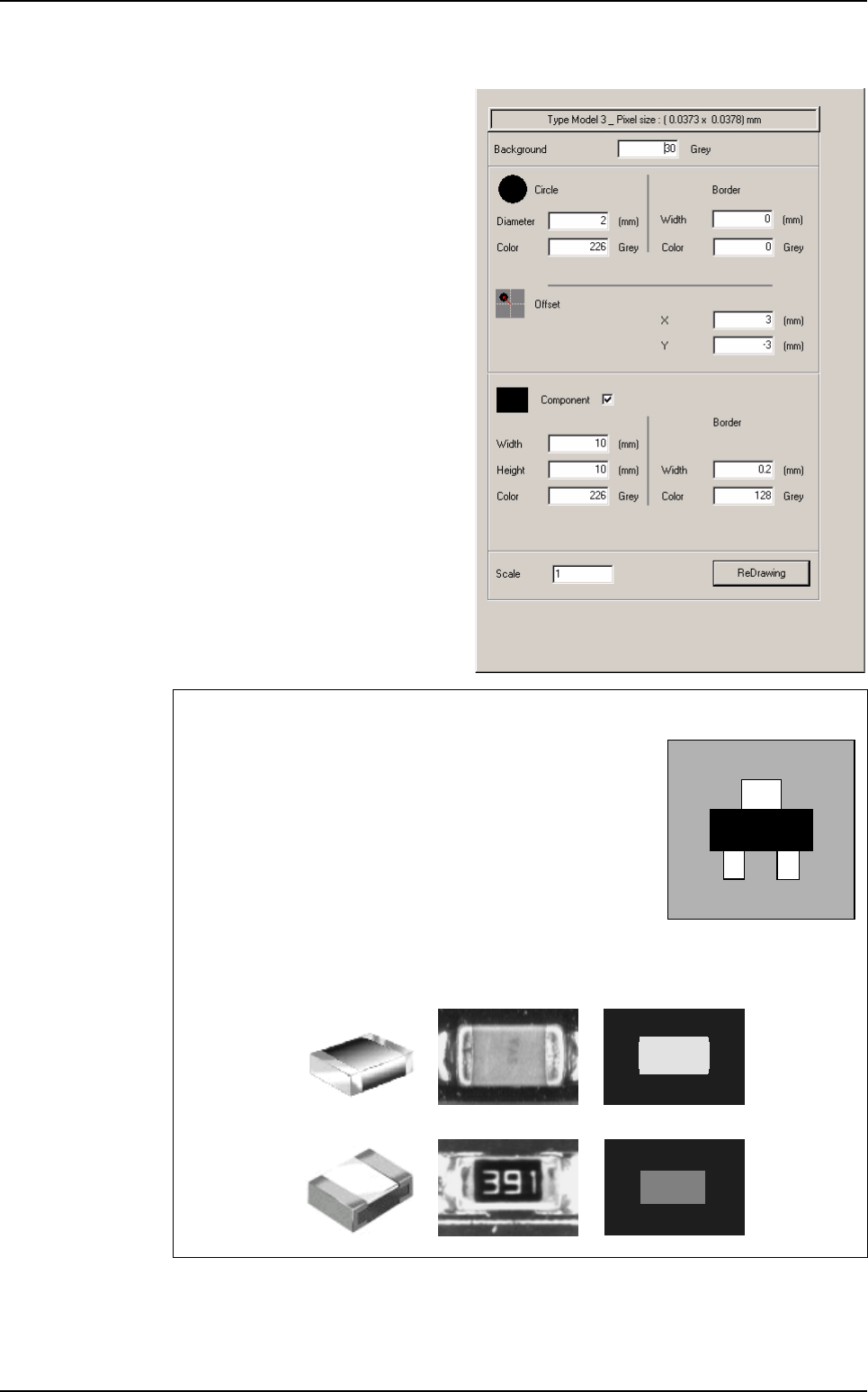
TYPE 3 component (with circle)
Specify the Background color in
gray levels (between 1 and 255).
Specify the Circle and Border di-
mensions and Color in gray levels
(between 1 and 255).
Specify the Offset between the circle
and the center of the component in
mm.
Specify the Component and Border
dimensions and color in gray levels
(between 1 and 255).
Specify the Scale of the component
you want to create (1 by default).
Press ReDrawing button at any time
to view the changes in the creation of
your component after modifications.
Gray levels
Black = 30: component or support (board).
White = 226: leads, pads or the support (board).
Gray = 128: component or support (board).
Note that the average difference between the colors is the same.
Only 3 gray levels are to be used in the creation of a synthetic
model.
Examples
Chip Capacitor
C3216 (C1206)
Component
image
Synthetic
image
Real
image
Chip Resistor
R3216 (R1206)
Component library
Tools library
7 - 8 Vision 2007 4.10 User Manual Rev 01
7.1.4 Creating synthetic models with Image Edit
7.1.4.1 Image Edit description
Images created by
Image Edit
are real images from the Full
board library, but modified to
extract, highlight or enhance
their features.
This allows to emphasise
what the inspection tools
should look for, and ignore
features that are not or less
important. This also results in
increased inspection perfor-
mance.
Select a representative pattern with consistent features. Reduce needless features and
image noise. Train only important features. Consider editing bitmaps to create a repre-
sentative pattern. Larger patterns will provide greater accuracy. High frequency features
are more significant at outer edges of patterns.
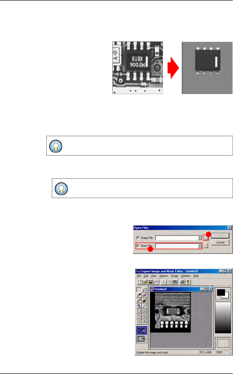
7.1.4.2 Image Edit using
1. Select ImgEdit in the Edit menu.
2. The Cognex Image and Mask Editor window appears (see below). A tool box to mod-
ify the image is presented: enhance the lines that you want to keep for the inspection,
or delete those that seem to be unimportant.
3. To display a component image, go
into the File menu and click Open
(Ctrl+O). The Open Files window
appears. Click this button (A) to
choose the real image of the model
that you want to modify and remove
the tick from Mask file (B).
4. The Image Edit window is activated,
with the selected image (lighting lev-
el) of the model.
5. Click on the Save icon in the tool bar
to save the modified image of the
model or select Save (Ctrl+S) in the
File menu then Exit in the same
menu to return to Vision 2007 main
screen.
6. Select Create model from current
series from the Models menu to en-
able the newly modified image to be
listed in the component library.
Image Edit is used to convert real images into synthetic images.
A library must be opened to access the Edit menu.
Original real image
Lines that are not important
to the inspection are deleted.
Synthetic image from Image Edit
A
B
Component library
Tools library
Vision 2007 4.10 User Manual Rev 01 7 - 9
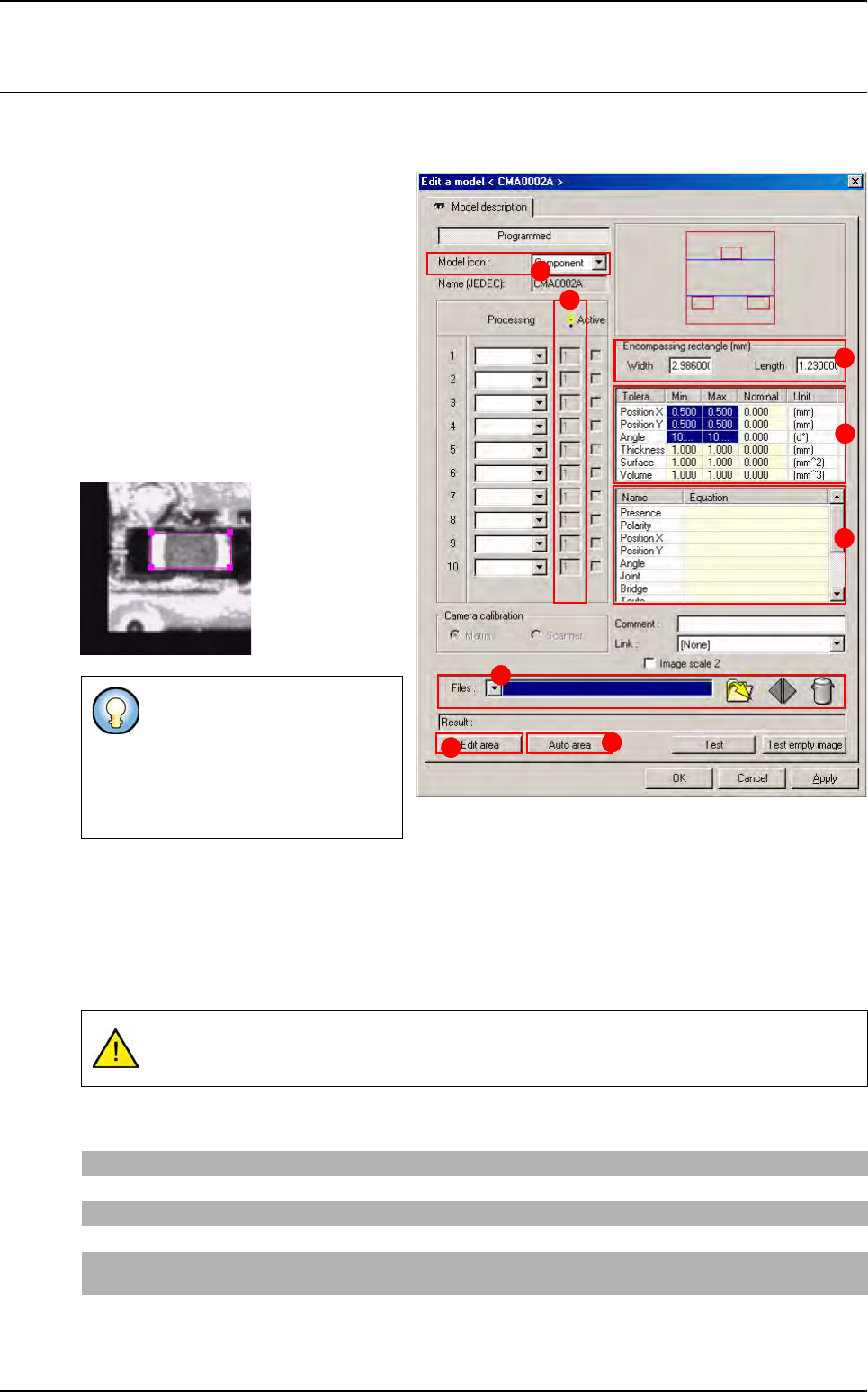
7.2 Model edition
With the library opened, double click on the model that you want to edit, to display the Edit a model
window.
1. Select the image of the component that
you want to program from the list avail-
able in Model image (A) to display the
selected image or browse the image with
this button.
2. Select in Model icon (B), the icon repre-
senting the type of component being
treated.
3. When you click on Edit the area (C) but-
ton a magenta contour appears in the
camera window. Drag and resize this
contour and outline the model image cor-
rectly.
Deactivate the Edit area function by clicking it again. The characteristics of the Encompassing rect-
angle are automatically filled in during step 3.
The Auto area (E) button enables positioning of the encompassing rectangle. The automatic area
edition can be performed if, and only if, the model used is a synthetic model.
4.
In
Tolerances (mm)
(
F
) section,
enter the inspection tolerances ( X, Y and Theta) for the current model.
5. In Equations (G) section, enter the equations to be used for component test.
This magenta rectangle called the
Encompassing
rectangle
(
D
) is
used to define the size of the com-
ponent in the library and therefore
in the associated .tst file during its
creation.
If the tolerances are zero, the inspection result will always be a position error (the perfect
position does not exist).
Presence
Enter the processing window number. If this is the window 1, part R1 (R for Result).
Polarity
Enter the window number in the different text fields if a component requires one of the tests mentioned.
Position X and Y
Enter X1 or Y1 to have the position of the tool in window 1.
Angle
Enter T1 in the Angle text field to indicate that the angle is calculated by the inspection tool of window 1.
Joint
Enter the processing window number. If this is the window 1, part 1-J1 (J for Joint), only if you have a SO
or QFP tool in the window 1.
Bridge
Enter the processing window number. If this is the window 1, part 1-B1 (B for Bridge), only if you have a
SO or QFP tool in the window 1
A
B
C
E
F
G
D
H