VI User Manual.pdf - 第174页
Tools library 7 - 12 Vision 2007 4.10 User Manual Re v 01 7.3.2.1 Vi-Pro parameters Configuration tab Click Configuration tab in the Parameters sec- tion to access functional and decision parame- ters. The Acceptable Sc …
Tools library
Vision 2007 4.10 User Manual Rev 01 7 - 11
7.3 Vi-Pro
Vi-Pro is a tool to recognize geometric shape based on vector analysis of the image and not pixel by
pixel. This geometry is based on the most contrasted transitions included in the image. Vi-Pro is used
to find the precise position of a component. It returns the presence, X, Y and Theta position of a com-
ponent.
7.3.1 Model description tab
1. On the Model description tab, in the Edit a model window, click on the button to add a
synthetic image of the model. The .bmp file name appears in picture list window. Select the
image on which to apply the treatment.
2. Click Auto area button to define the component size.
3. Choose the treatment operation: Vi-Pro. A new Vi-Pro tab appears behind the Model de-
scription tab.
4. With the Autotooling, the model is automatically trained.
5. On the Model description tab, in the Edit a model window, choose the treatment operation:
Vi-Pro. A new Vi-Pro tab appears behind the Model description tab.
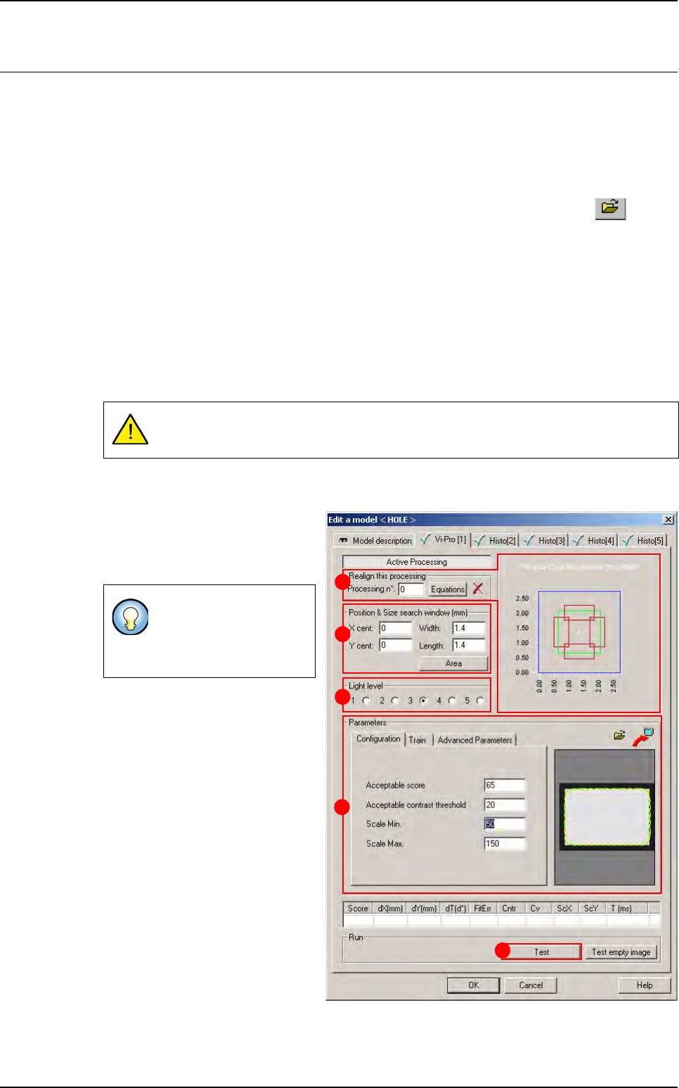
7.3.2 Vi-Pro tab
1.
Use
Realign this processing
(
A
)
section if you want to realign the po-
sition of the tool with another one
(not available for window 1).
2.
In
Position & size model window
(mm)
(
B
)
section,
enter the size and
position of the search window (zone
in which the component will be
searched for). These dimensions
must be larger than the Vi-Pro train
area by at least the component toler-
ance.
3.
In
Light level
(
C
) section, select the
light level to use.
4. In Parameters (D) section, enter
the Vi-Pro parameters (see below
7.3.2.1 Vi-Pro parameters).
5.
Click
Test
(
E
) button to test the Vi-
Pro tool and display the results (see
below
7.3.2.2 Vi-Pro test
).
Model training with Vi-Pro is only possible with a synthetic image.
If you need a special
equation to realign, you
can do so using the
Equations button.
A
B
C
D
E
Tools library
7 - 12 Vision 2007 4.10 User Manual Rev 01
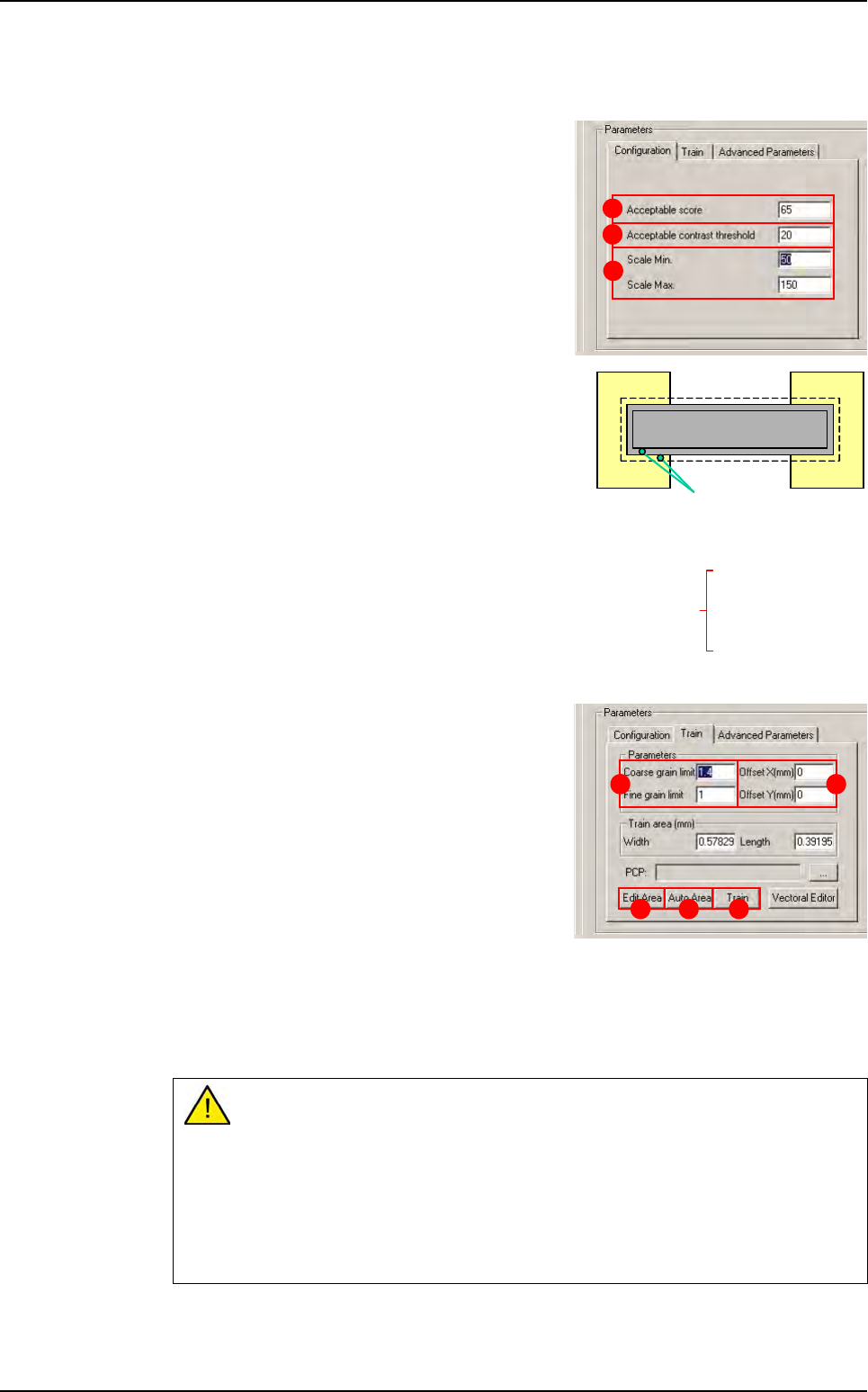
7.3.2.1 Vi-Pro parameters
Configuration tab
Click Configuration tab in the Parameters sec-
tion to access functional and decision parame-
ters.
The Acceptable Score (A) only considers the
coverage result of the test. This value is the mini-
mumthreshold at which the treatment result is ac-
cepted. If the treatment score is lower than this
threshold, the test result will be a score of zero.
The Acceptable contrast threshold (B) is de-
fined as the difference of an identified transition.
This value is the minimum threshold at which a tran-
sition will be accepted. Contrast is defined by a gray
level value. When you test the Vi-Pro tool, the con-
trast result should be above 80. This ensures ade-
quate definition between the foreground and
background and reduces the number of false de-
fects in production.
The Scale Min/Max (C) is the degree of freedom for
Vi-Pro model to allow uniform scale change for the
component.
Train tab
Click the Train tab to access the training in the
model characteristics.
The Coarse grain limit and Fine grain limit (A)
parameters are used to define the size of the vec-
tors used to detect transitions.
Large transitions are detected with the Coarse
grain limit or Fine grain limit, and small transi-
tions are detected with the Fine grain limit.
Vi-Pro uses the range created by the Coarse
grain limit and Fine grain limit limits:
Treatment speed is determined by the Coarse grain limit.
Treatment accuracy is determined by Fine grain limit.
The grain limit informs Vi-Pro which vectors have been detected in the image. The values
given by default are, in most cases, the most suitable.
If you increase the grain limit, Vi-Pro loses detection details.
Increase the Coarse grain limit:
- Increases treatment speed.
- Reduces accuracy.
- Body detection (reduces fine detection).
Reduce the Fine grain limit:
- Reduces treatment speed.
- Increases accuracy.
A
B
C
0 = black
256 gray levels
255 = white
20 - 40 (B)
150 -200 (A)
1
5
0
-
2
0
0
(
A
)
transitions
Contrast = A - B
Result ~ 100 (perfect score)
A B
D EC
Vi-Pro
Tools library
Vision 2007 4.10 User Manual Rev 01 7 - 13
The Offset XY (mm) (B) is a shift in the geometric center of the component from its the-
oretical center.
Press Auto area (C) button to place the Vi-Pro tool train area exactly around the model.
Press Edit area (D) button to adjust the train area manually. The
handles appear on the red contour outlining the component in the
display screen.
Click on the red contour and adjust it so that it is 3 - 4 pixels larger
than the component itself.
Click ZOOM + to enlarge the image of the component in the dis-
play window.
Click PIXEL MAPPING to display the grid on the screen.
Click Train (E) to learn the Vi-Pro pattern.
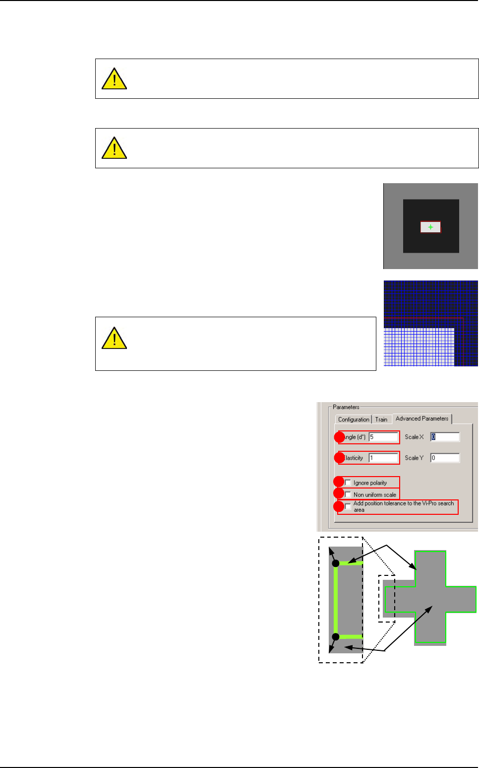
Advanced parameters tab
Click Advanced parameters tab to access other
characteristics.
The Angle (d°) (A) is the degree of freedom for
Vi-Pro to find the component in the search area.
The Elasticity (B) is the degree of tolerance that
Vi-Pro will accept for non linearity of the compo-
nent. The elasticity unit is the pixel. Elasticity is
used to stretch or reduce the size of components
in all directions at once.
Repeat model training after any offset changes.
The Auto area function automatically positions this training area.
A window that is not centered on your training model will
result in a permanent position shift in the inspection re-
sults.
A
C
E
B
D
Image
Pattern
Vi-Pro