VI User Manual.pdf - 第176页
Tools library 7 - 14 Vision 2007 4.10 User Manual Re v 01 Tick Ignore polarity ( C ) to evaluate th e transition vectors with different polarities. The model's po larity is defined at each poi nt in the transitions …
Tools library
Vision 2007 4.10 User Manual Rev 01 7 - 13
The Offset XY (mm) (B) is a shift in the geometric center of the component from its the-
oretical center.
Press Auto area (C) button to place the Vi-Pro tool train area exactly around the model.
Press Edit area (D) button to adjust the train area manually. The
handles appear on the red contour outlining the component in the
display screen.
Click on the red contour and adjust it so that it is 3 - 4 pixels larger
than the component itself.
Click ZOOM + to enlarge the image of the component in the dis-
play window.
Click PIXEL MAPPING to display the grid on the screen.
Click Train (E) to learn the Vi-Pro pattern.
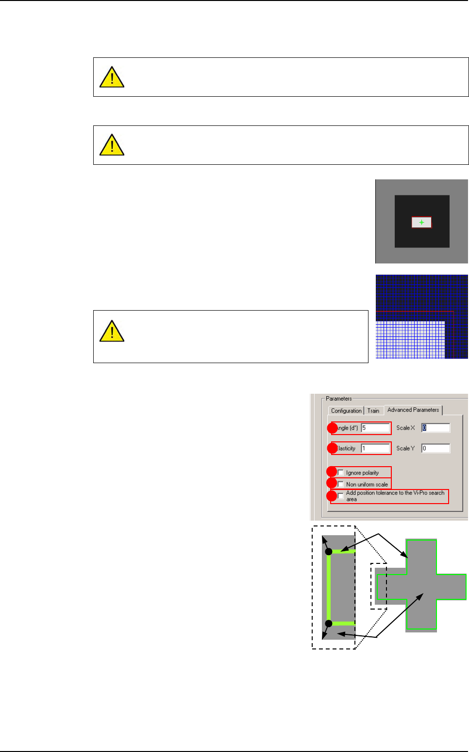
Advanced parameters tab
Click Advanced parameters tab to access other
characteristics.
The Angle (d°) (A) is the degree of freedom for
Vi-Pro to find the component in the search area.
The Elasticity (B) is the degree of tolerance that
Vi-Pro will accept for non linearity of the compo-
nent. The elasticity unit is the pixel. Elasticity is
used to stretch or reduce the size of components
in all directions at once.
Repeat model training after any offset changes.
The Auto area function automatically positions this training area.
A window that is not centered on your training model will
result in a permanent position shift in the inspection re-
sults.
A
C
E
B
D
Image
Pattern
Vi-Pro
Tools library
7 - 14 Vision 2007 4.10 User Manual Rev 01
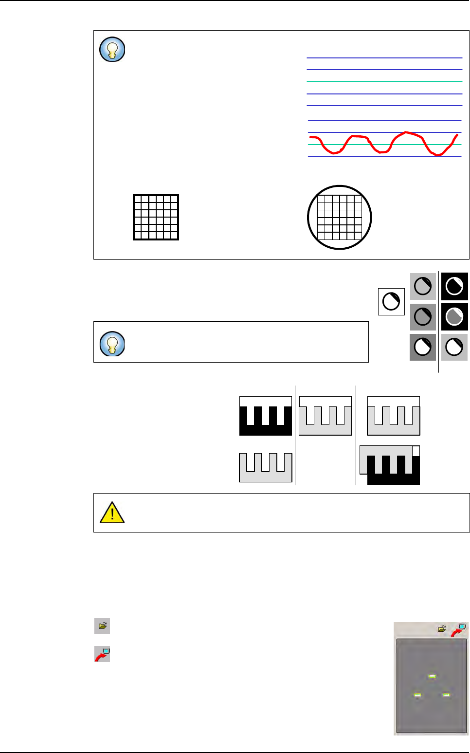
Tick Ignore polarity (C) to evaluate the transition vectors with
different polarities. The model's polarity is defined at each point
in the transitions as the transition direction (black => white or
white => black) and is not dependent on amplitude.
You can configure Vi-Pro to ig-
nore the model's polarity and only
use the shape vector information.
Polarity is a Vi-Pro parameter
which can make model corre-
spondence less ambiguous.
You should ignore polarity only
when the object is subject to po-
larity changes.
The Non uniform scale (D) tick box allows Vi-Pro to stretch the trained model in X or Y
and run a non-uniform scale. It can increase accuracy but is time consuming.
Tick Add position tolerance to the Vi-Pro search area (E) to add, the model's position
tolerances to the Vi-Pro search area at execution time.
Train image window
Save as you want the image extracted from Vi-Pro train and use
it as another synthetic image.
Load the Vi-Pro train in the COGNEX console.
Standard setting: between 0 and 1 (Max 6.0).
If you change the value to 0, only the
transitions near the straight line will be
detected. Detection accuracy is higher
but the transitions must be close to the
trained model.
If you change the value to 1, transitions
detected will be between 1 and -1 pix-
el. Accuracy is improved but the num-
ber of detections is reduced.
By default, Vi-Pro only recognizes models with the
same polarity as the trained model.
Incorrect use of this parameter may lead to false detections.
0*
* the model is perfect
1
0
-1
Elasticity = 0
If elasticity = 2,
then it detects
a circle!
Trained
model
Same
polarity
Different
polarity
Object
PatMax model
PatMax
using polarity
PatMax
ignoring polarity
Expected
correspondence
Incorrect
correspondence
Vi-Pro
Tools library
Vision 2007 4.10 User Manual Rev 01 7 - 15
7.3.2.2 Vector tool model creator
Presentation
Option available on Vi-Pro model.
Vector tool model creator allows to create model by
using mouse on a real image.
It is really easy and
fast, you just have to click on vertex along the shape.
Vector tool model creator is helpful for the vector
model programming. It is easier and faster to program
new model and more accurate if you directly enter the
component size in vertex table.
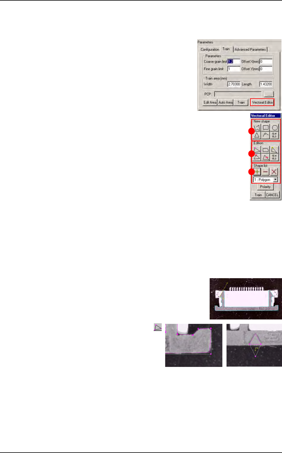
In Train tab, click on Vectoral Editor button, this win-
dow appears:
In New shape (1) part, buttons allow to add different kind of shape using
the mouse.
Several continuous segment (opened or closed shape)
A rectangle
A circle
A triangle
A square angle
Or if you know the exact component dimensions, click on button to enter
directly component vertex position in a table.
In Edition (2) part, buttons allow to edit vector.
In Shape list (3) part, buttons allow to manage several different and discontinuous
shapes in one model.
How to use Vector tool model creator ?
1. In Model description tab, create a Vi-Pro model and select the image.
2. In Vi-Pro tab, go to Train tab and click on Vectoral Editor button.
3. Create the shape with New shape button. Draw the
shape by using mouse on the image.To finish the
shape, double click.
4. To see and move a vertex press
button, then drag and drop the vertex
by clicking on it and move it.
1
2
3
Vi-Pro