VI User Manual.pdf - 第180页
Tools library 7 - 18 Vision 2007 4.10 User Manual Re v 01 Recommendations f or using Vi-Pro Choose a representative synthetic model with clea r lines Delete unimportant lines and imag e noise. Only train important …
Tools library
Vision 2007 4.10 User Manual Rev 01 7 - 17
When to use Vector Tool Model Creator ?
Vector Tool Model Creator option can be used among other:
To create a model of complex shape.
To create model of opened shape. This ability could be very
useful for components whose part of edge is not visible.
To create model without certain segment (choose rep-
resentative segment for the model).
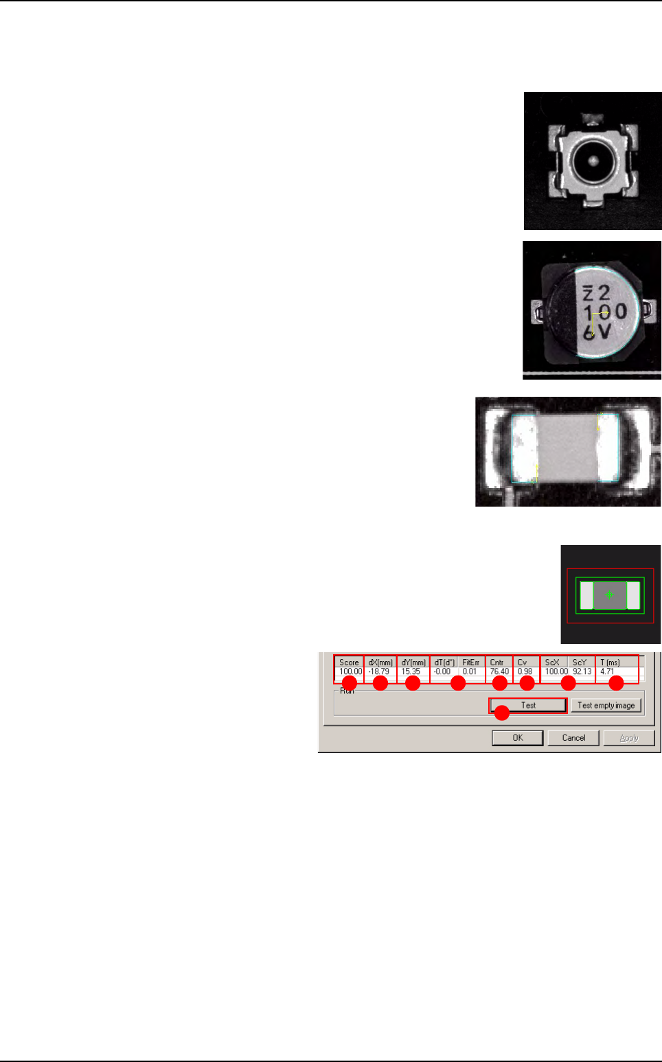
7.3.2.3 Vi-Pro test
Click on Test (A) button to apply all the inspection parameters to the
model, then a fiducial representing the center of the model will appear
in the camera window.
Score (B): score of the test-
ed tool (rate of detection suc-
cess).
dXY(mm) (C): position in X
and Y of the model found with
respect to the center of the
model’s encompassing area.
dT(d°) (D): position result in theta of the tested model.
FitErr
(Vi-Pro algorithm) (
E
): the closer the measurement is to 0, the better the model is.
Cntr (F): difference of a transition, in gray level values between background brightness
and component brightness. This value is the average of the transition contrast found dur-
ing the test.
Cv (
Vi-Pro
algorithm) (G): the coverage measures the percentage of vectors found in the
image of the search window with respect to the trained model:
The more vectors found, the closer the result will be to 1.
The fewer vectors found, the closer the result will be to 0.
ScXY (H): scale of the model found with respect to the trained model.
T (ms) ( I ): inspection time.
A
B C D E F G H I
Vi-Pro

Tools library
7 - 18 Vision 2007 4.10 User Manual Rev 01
Recommendations for using Vi-Pro
Choose a representative synthetic model with clear lines
Delete unimportant lines and image noise.
Only train important lines.
A large model will be more accurate.
Search window size affects inspection time (width) x (length) x (search angle).
Reduction of the Fine grain limit parameters increases inspection time.
Increase of the Coarse grain limit parameters reduces inspection time.
Consideration of polarity slightly increases inspection time.
Set a Contrast Threshold greater than 0.0 to accelerate inspection.
Vi-Pro
Tools library
Vision 2007 4.10 User Manual Rev 01 7 - 19
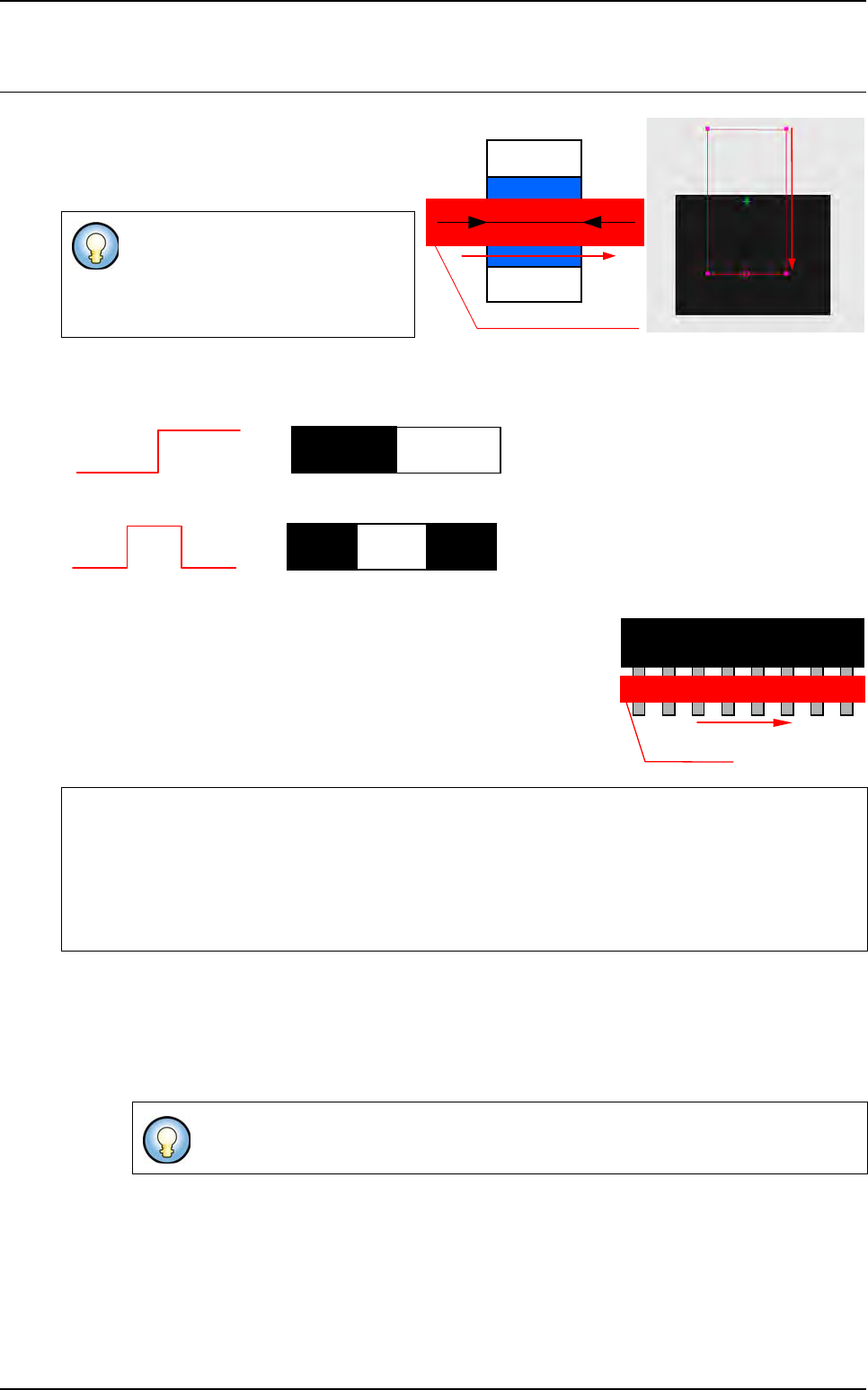
7.4 Edge
The Edge tool operates by detection of grey
level transitions. It is used to calculate an X or
Y position of a component or to check the po-
larity of the components.
You can detect 1 or 2 transitions:
1 transition
2 transitions
Enables you to find a defined number of identical transitions within a
limited area.
Enables you to find the center of 2 distant transitions of a pre-defined
length.
7.4.1 Model description tab
1. On the Model description tab, in the Edit a model window, choose the treatment operation:
a new Edge tab appears behind the Model description tab.
2. Click Edit area button to define the component location in the image.
The Edge tool measures only 1 di-
rection.
Very accurate measurement tool (1/
10 pixel).
If the edge tool is used to find a defined distance between
2 transitions, tolerance must not be 0.
If you use synthetic model you can use
Auto area button.
Detection area and direction
Component
Width
Detection
direction
0
255
0
255
0
255
0
00
255
Treatment direction
Treatment area
1
st
2
nd
N
th