VI User Manual.pdf - 第189页
Tools library Vision 2007 4.10 User Manua l Rev 01 7 - 27 7.6.2.1 BGA parameters General section Select the Color ( A ) of the component to de termine the edge polarity. If necessary indicate the Off- set X & Y (mm) …
Tools library
7 - 26 Vision 2007 4.10 User Manual Rev 01
7.6 BGA
The BGA tool is dedicated to the detection of BGA components. For this detection, we use edge tools
exclusively. The polarity of these edges is determined by the component color.
7.6.1 Model description tab
1.
On the
Model description
tab, in the
Edit a model
window, click on the button . The .bmp
file name appears in picture list window. Select the image on which to apply the treatment.
2. Click Edit area button to define the component size.
3. Choose the treatment operation: a new BGA tab appears behind the Model description tab.
All treatment windows (position & size) are automatically created according to the encom-
passing rectangle definition.
4. With the Autotooling, the model is automatically trained.
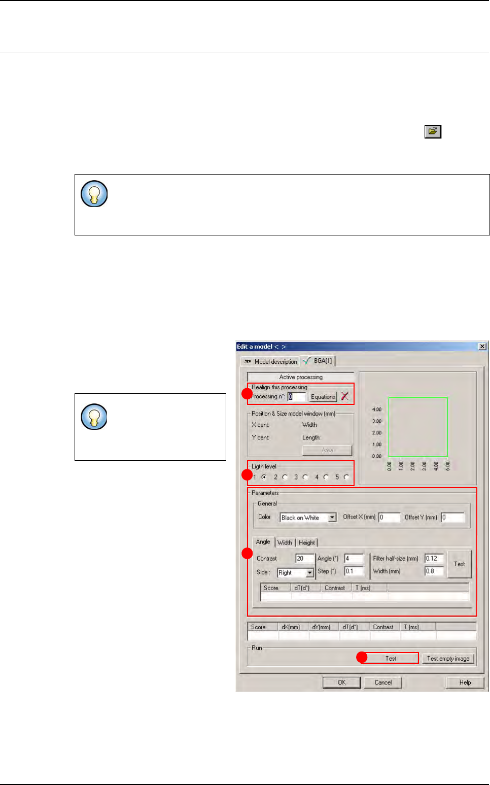
7.6.2 BGA tab
1.
Use
Realign this processing
(
A
)
section if you want to realign the po-
sition of the tool with another one
(not available for window 1).
2.
In
Light level
(
B
)
section, select the
light level to use.
3. In Parameters (C) section, enter
the BGA tool parameters (see be-
low § 7.6.2.1 BGA parameters).
4. Click Test (D) button to test the
BGA tool and display the results
(see below § 7.6.2.2 BGA test).
When you create a BGA, use the encompassing rectangle dimension to initialize
BGA tool dimension.
When you use synthetic model, click on
Auto area
button to define the component size.
If you need a special
equation to realign, you
can do so using the
Equations button.
B
A
C
D
Tools library
Vision 2007 4.10 User Manual Rev 01 7 - 27
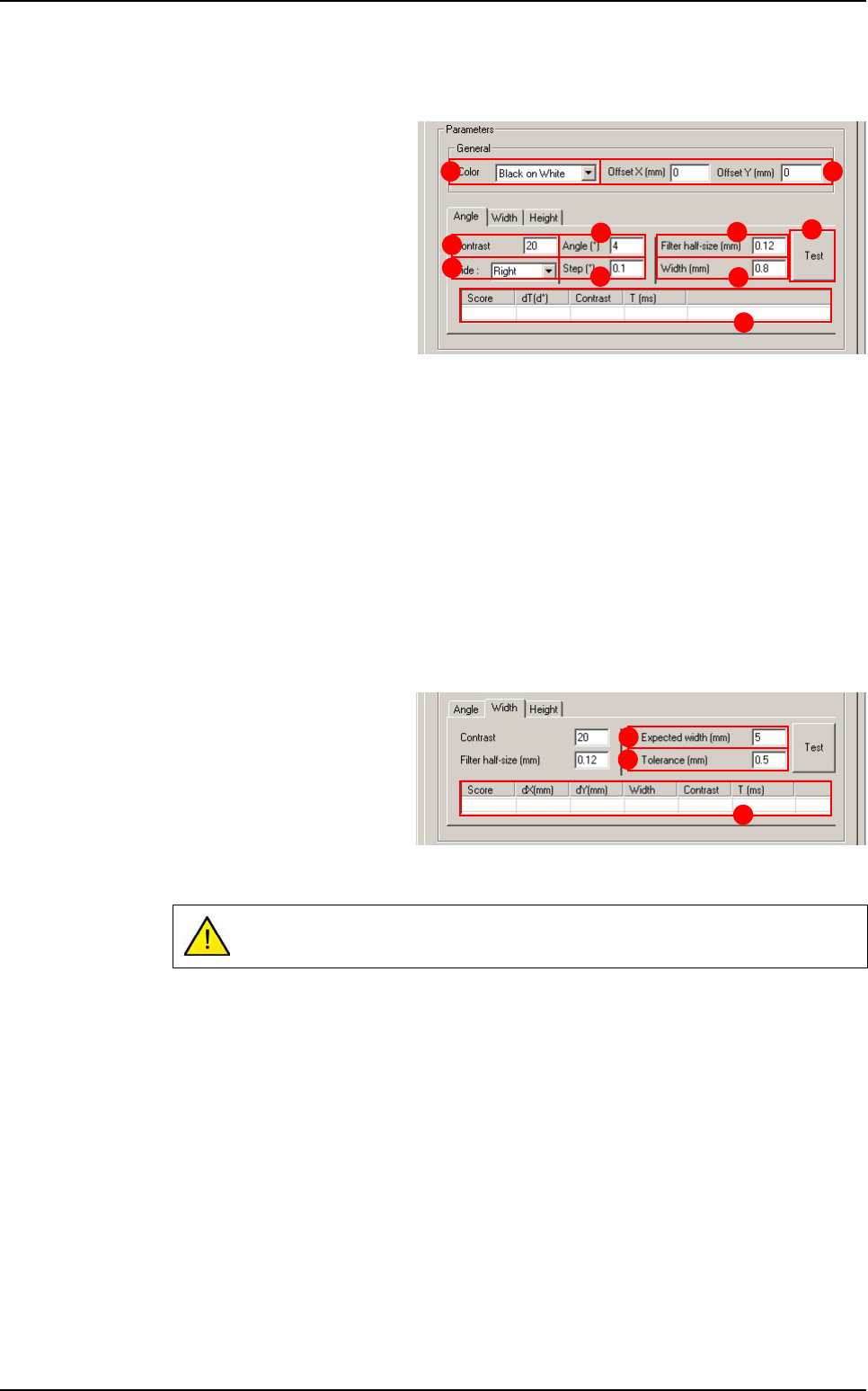
7.6.2.1 BGA parameters
General section
Select the Color (A) of the
component to determine the
edge polarity.
If necessary indicate the Off-
set X & Y (mm) (B) from CAD
position.
Angle tab
Contrast (C): minimum contrast transition.
Side (D): side of BGA to test.
Angle (°) (E): search angle.
Step (°) (F): search angle accuracy.
Filter half size (mm) (G): filter half size of edge.
Width (mm) (H): width of turning edge.
Press Test ( I ) button to test the angle detection.
Angle test result (J).
Width & height tabs
The parameters are the
same for Width and Height
detection.
Expected width (mm) (K) of
the component.
Tolerance (mm) (L) on ex-
pected width.
Width or Height test result (M).
If you have not tested the
Angle
before,
Width
and
Height
are tested at 0°.
A B
E
C
F
H
G
I
J
D
L
K
M
BGA
Tools library
7 - 28 Vision 2007 4.10 User Manual Rev 01
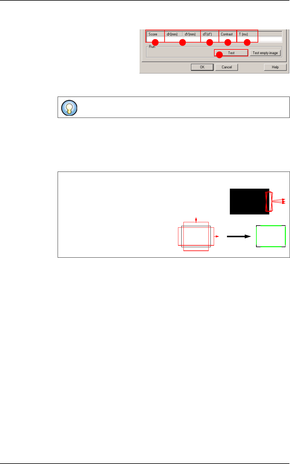
7.6.2.2 BGA test
Click on Test (A) button to
apply all the inspection pa-
rameters to the model.
Score (B): score of the tested
tool (rate of detection suc-
cess).
dX&Y(mm) (C): position in X and Y between the transitions (centre between the 2 tran-
sitions).
dT(d°) (D
): position result in theta of the tested model.
Contrast (E): difference of a transition, in gray level values between background bright-
ness and component brightness. This value is the average of the transition contrast
found during the test.
T (ms) (F): inspection time.
If only one transition is looked for, this is the position of the transition found.
Angle and postion detections
The BGA angle is detected by a turning edge. This edge re-
turns the angle that gave the best contrast in its search angle.
BGA position detection is returned by 2
double transition edges.
These 2 double transition edges return the
X and Y position of the BGA component.
A
B C D E F
Scoring by size
and contrast
BGA