VI User Manual.pdf - 第199页
Tools library Vision 2007 4.10 User Manua l Rev 01 7 - 37 7.8.2 Custom tab The Cu stom tool is based on the QFP tool. When opening the custom edit page, all th e treatment areas are automatically placed a ccording to the…
Tools library
7 - 36 Vision 2007 4.10 User Manual Rev 01
7.8 Custom
The Custom tool is available in the library to inspect automatically exotic SO and QFP components or
connectors. To inspect solder joints and bridges on components with a different number of pins, with
pins of different size and position and color:
You can set different parameters for each pin.
You can test and active each pin individually.
The component detection is made in 2 steps:
Body detection.
Leads detection.
After finding the precise component position, each joint and bridge inspection tool is automatically
placed. This tool can be used for multizones components (the only difference is the body detection).
7.8.1 Model description tab
Follow this procedure to easily program a
component.
1. Draw a synthetic image with Build Model
Type 2. You can still program a custom
model if you do not have any synthetic
image.
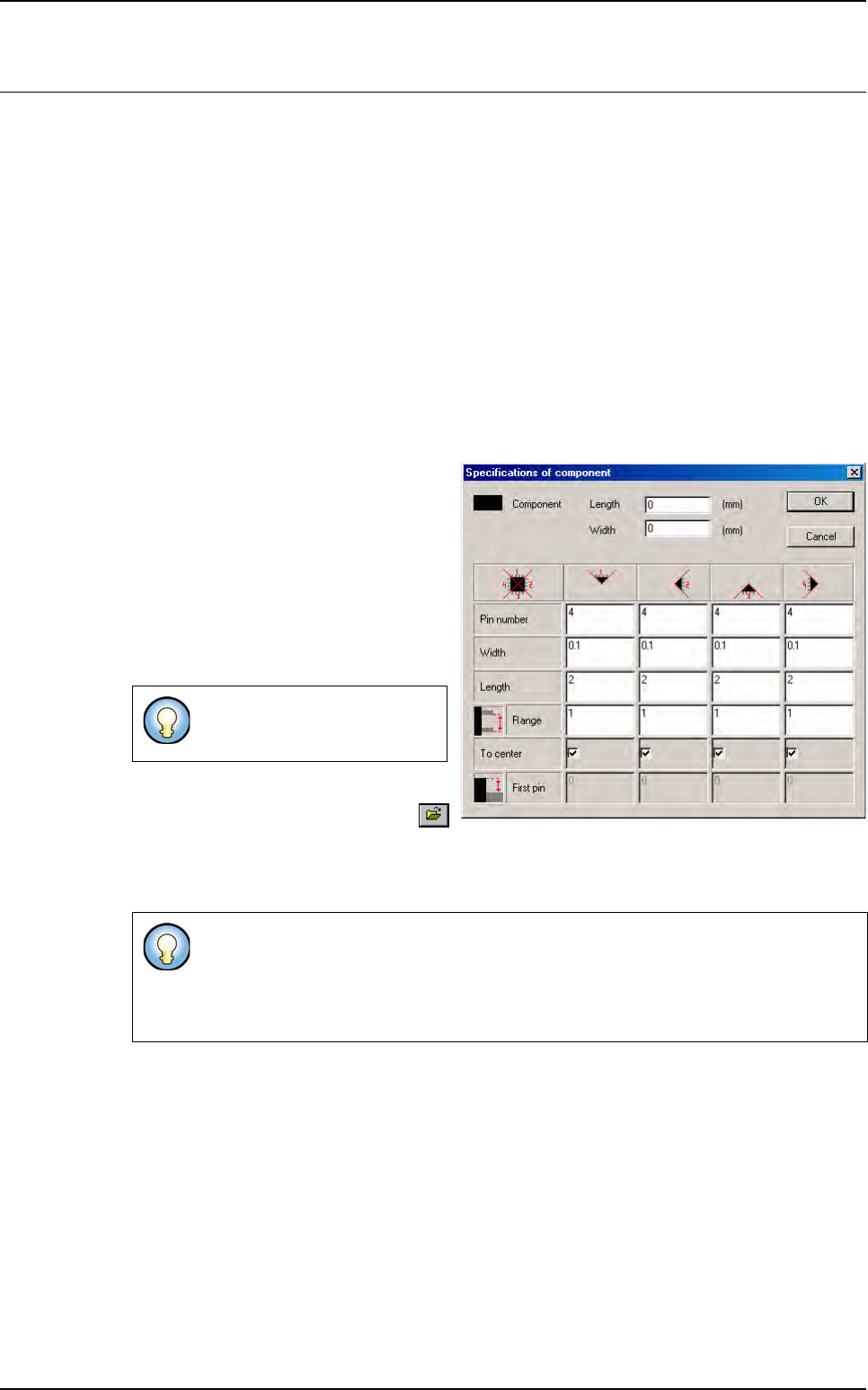
2. When opening the custom edition, enter
all the component features in the oppo-
site window.
3. On the Model description tab, in the
Edit a model window, click on the
button. The bmp file name to add in picture list window appears. Select the image on which
load the treatment.
4. Click on Edit area button to define the component size.
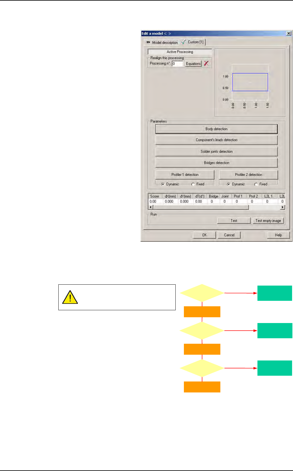
5. Choose the treatment operation: Custom, a new tab appears (with the inspection tool name)
behind the Model description tab.
The Custom tool is based on the QFP tool. When opening the custom edit page, all the treat-
ment areas are automatically placed according to the component features. You just have to
check that these parameters fit on real components.
Load a real image on the camera display and adapt the parameters.
You can just create regular SO
and QFP on this interface.
When you create a Custom, use the encompassing rectangle dimension to initialize
Custom tool dimension.
When you use synthetic model, click on
Auto area button to define the component
size.
Tools library
Vision 2007 4.10 User Manual Rev 01 7 - 37
7.8.2 Custom tab
The Custom tool is based on the
QFP tool. When opening the custom
edit page, all the treatment areas are
automatically placed according to the
component features.
Check that these parameters fit on
real components.
Load a real image on the camera dis-
play and adapt the parameters.
7.8.3 Body detection
7.8.3.1 Algorithm
If one of these 3 steps fails, the
component is missing.
Missing
component
Missing
component
Missing
component
Return Theta
Angle
detection
fails ?
Return X
Width
detection
fails ?
Return Y
Height
detection
fails ?
Yes
Yes
Yes
No
No
No
Custom
Tools library
7 - 38 Vision 2007 4.10 User Manual Rev 01
7.8.3.2 Parameters
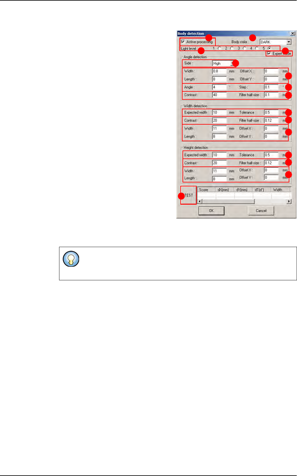
Tick Active processing (A) to active the
component body detection.
In Body color (B) select the color of the
component body (dark or bright).
Select the Light level (C) used for the
body detection.
In Angle detection section, define the pa-
rameters for the component angle detec-
tion. The body angle detection is done
with an helicopter Edge:
Select the Side (D) of the component you
want to use for the angle detection.
Offset XY, Width and Length (E) of the
edge window.
Angle and Step (F) of rotation for the ro-
tating edge.
Contrast and Filter Half-size (G) edge
tool parameters for detection.
In Width and Height detection sections,
define the parameters for the component
width and height detection.
Expected width and Tolerance (H) of the
body width.
Contrast and Filter Half-size ( I ) edge tool parameters for detection.
Offset XY, Width and Length (J) of the edge window.
Press TEST (K) button to execute the 3 previous detections and see the results.
Expert mode (L) allows to access all parameters of this window. If this window is not
ticked, only some parameters are displayed.
The width and height body detection are done with 2 double transitions edges.
The edge windows are realigned with the results of the previous step (the 1st
step is the Angle detection).
A B
C
D
E
F
G
H
I
J
K
H
I
J
L
Custom