VI User Manual.pdf - 第201页
Tools library Vision 2007 4.10 User Manua l Rev 01 7 - 39 7.8.4 Components leads detection 7.8.4.1 Algorithm 7.8.4.2 Parameters Without Expert Mode The option Expert mode ( J ) is not ticked. Select the tab to edit the w…
Tools library
7 - 38 Vision 2007 4.10 User Manual Rev 01
7.8.3.2 Parameters
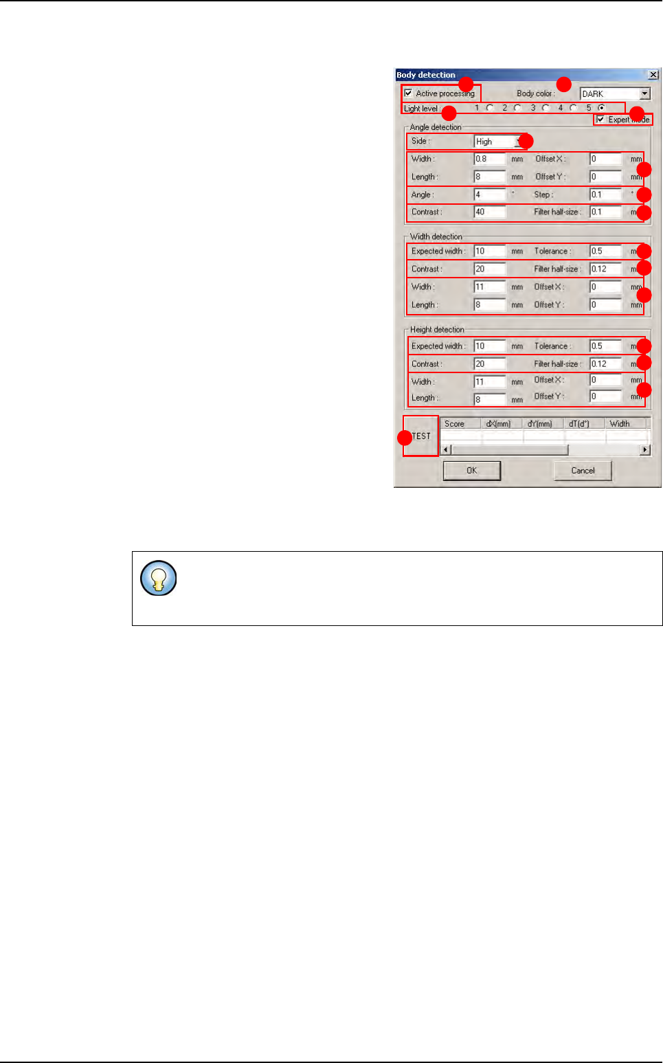
Tick Active processing (A) to active the
component body detection.
In Body color (B) select the color of the
component body (dark or bright).
Select the Light level (C) used for the
body detection.
In Angle detection section, define the pa-
rameters for the component angle detec-
tion. The body angle detection is done
with an helicopter Edge:
Select the Side (D) of the component you
want to use for the angle detection.
Offset XY, Width and Length (E) of the
edge window.
Angle and Step (F) of rotation for the ro-
tating edge.
Contrast and Filter Half-size (G) edge
tool parameters for detection.
In Width and Height detection sections,
define the parameters for the component
width and height detection.
Expected width and Tolerance (H) of the
body width.
Contrast and Filter Half-size ( I ) edge tool parameters for detection.
Offset XY, Width and Length (J) of the edge window.
Press TEST (K) button to execute the 3 previous detections and see the results.
Expert mode (L) allows to access all parameters of this window. If this window is not
ticked, only some parameters are displayed.
The width and height body detection are done with 2 double transitions edges.
The edge windows are realigned with the results of the previous step (the 1st
step is the Angle detection).
A B
C
D
E
F
G
H
I
J
K
H
I
J
L
Custom
Tools library
Vision 2007 4.10 User Manual Rev 01 7 - 39
7.8.4 Components leads detection
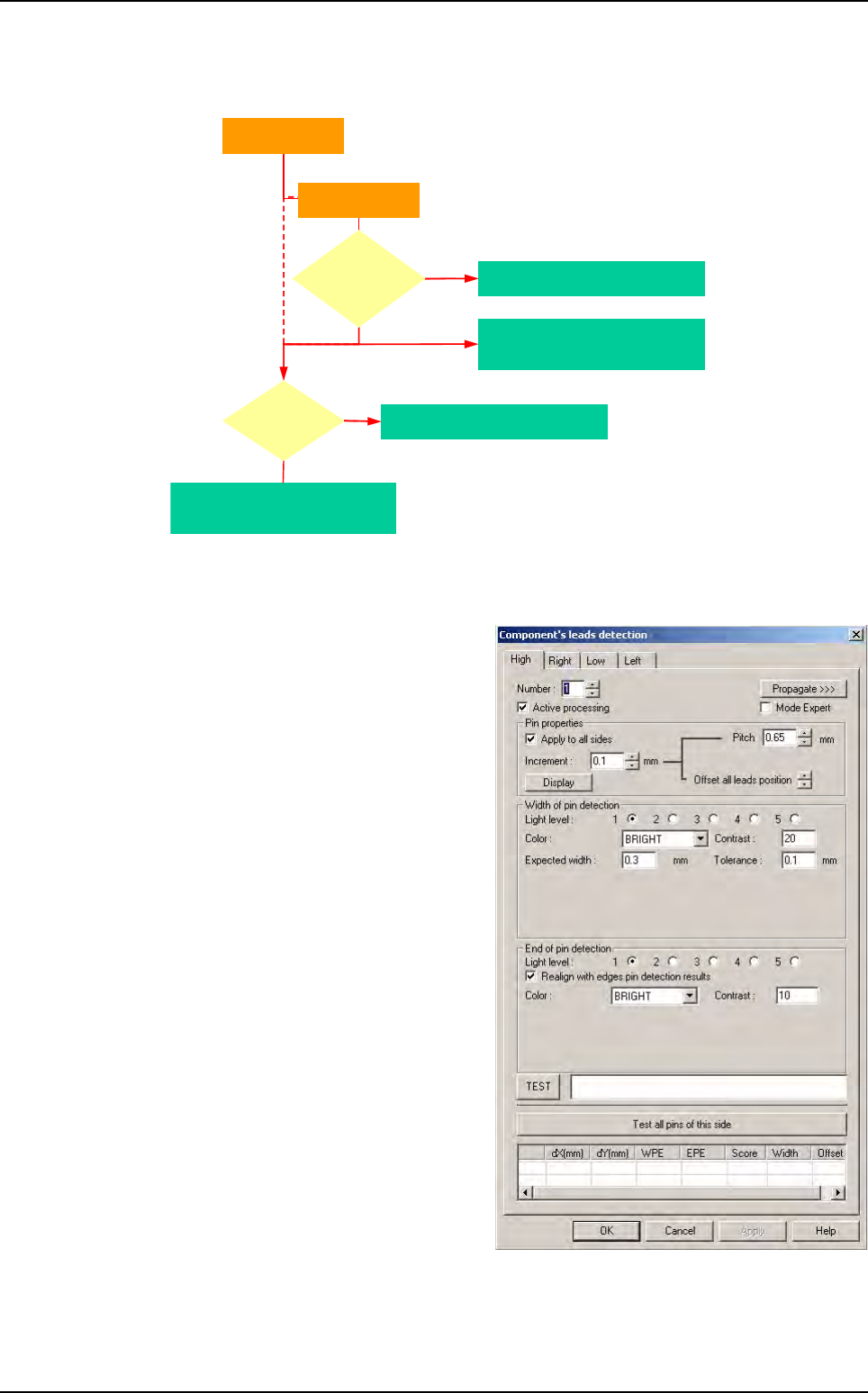
7.8.4.1 Algorithm
7.8.4.2 Parameters
Without Expert Mode
The option Expert mode (J) is not
ticked.
Select the tab to edit the wanted side of
1st component.
Select the pin number (
A
) you want to edit.
The Pitch (B) allows you to increase or
decrease the pitch size between pins.
With Offset all leads position (C) you
can modify the offset of all leads.
Tick Apply to all sides (D) to apply
these modifications to all sides.
Click on Display (E) button to see
modifications in the image window.
Increment (F) determine the value of
increase (or decrease) of pitch and off-
set of leads.
Missing lead
Yes
All pins are
missing ?
Missing component
Yes
Return fine X, Y, Theta
of the component
No
Return fine X, Y, Theta
of the lead for joint realignment
For each pin
For each side
Width
& end of lead
detection
fails ?
Custom
Tools library
7 - 40 Vision 2007 4.10 User Manual Rev 01
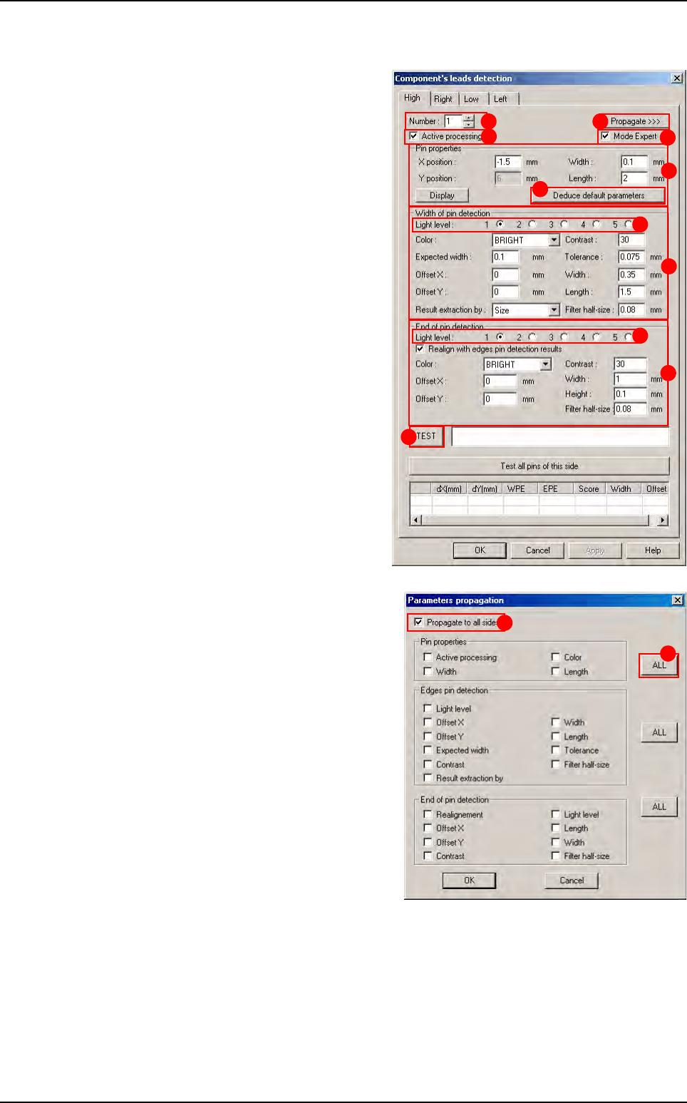
With Expert Mode
Tick the Expert mode (J) to display this
window.
Select the tab to edit the wanted side of
the component.
Select the pin number (
A
) you want to edit.
For the selected pin of the selected side,
tick
Active processing
(
B
) to run the
detection and select the
Light level
(
C
).
In Pin properties (D) section, enter the
features of the selected pin. Ensure
changes to adapt the model to reality. If
you change any parameters, press De-
duce default parameters (E) button to
change automatically the linked treat-
ments (solder joints and bridge detec-
tion).
In Edges pin detection (F) section,
enter the various parameters.
In End of pin detection (G) section,
enter the various parameters.
Press TEST (H) button to test of the
selected pin.
When you click on Propagate >>> ( I )
button, in order to propagate the different
parameters to all the sides, the opposite
window appears.
Tick Propagate to all sides (1) to propa-
gate the ticked parameters to all sides of
the component. Otherwise they will be
propagated to all pins of the selected
side.
Click on ALL button (2) to tick or not all
the parameters from the section.
A
B
D
E
F
G
I
H
J
C
C
1
2
Custom