VI User Manual.pdf - 第208页
Tools library 7 - 46 Vision 2007 4.10 User Manual Re v 01 7.9.2 Profiler™ tool using Choose the tr eatment operation: a new Custom tab app ears behind the Model description tab. Click on it, the window below appears. 1. …
Tools library
Vision 2007 4.10 User Manual Rev 01 7 - 45
7.9.1.1 Global adjustment tool principle
This tool is based on a comparison with fixed reference (a good lead/joint). Tolerances
are constructed in relation to this reference. This reference is defined on several good
leads. For this, a reference profile is done on a good lead, and tolerances are constructed
in relation to this reference. So they are fixed for all components of a same models. Each
profile out of tolerances is considered as bad.
7.9.1.2 Lead to Lead tool principle
This tool allows to adapt to the variations
of aspect related to a change in the pro-
duction (aspect of the welding, aspect of
the component leads…). It is not sensi-
tive to difference between components.
For the lead to lead tool, the comparison
is with the average of all profiles of the
components.
This tool is based on a comparison with
adaptive reference.
Tolerances are auto-
matically adjusted for
each component of a
same model. Toleranc-
es are adaptive.
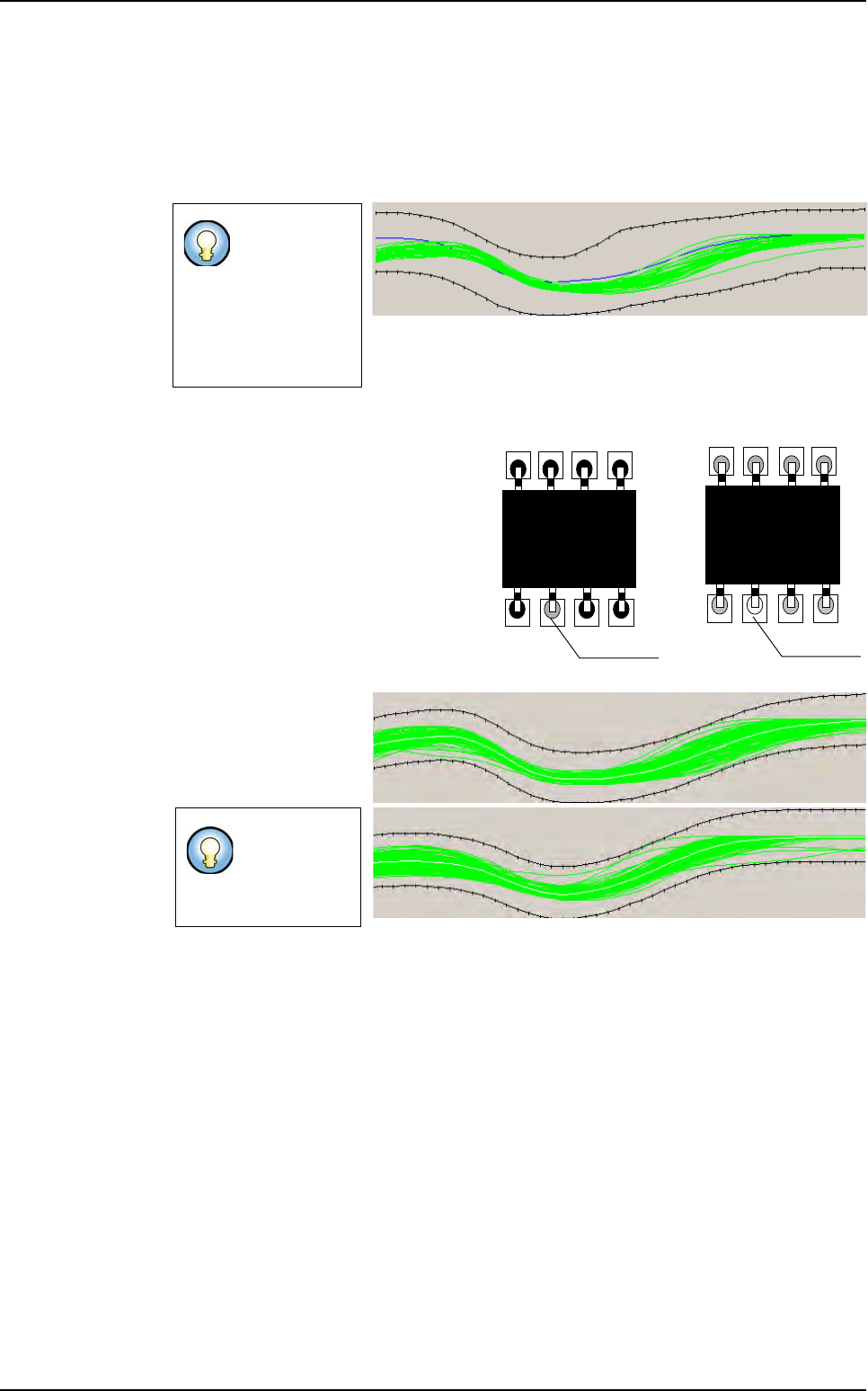
By using these 2 methods simultaneously, bad leads can be detected on joint by taking
into account of variation of production.
Tolerance must
be large to in-
clude all possible
variations of pro-
duction (lead and
welding aspect,
lead size ...).
Tolerances
could be tight
to detect more
defects.
Bad welding
Bad welding
Component A
Component B
Profiler
™
in Custom
Tolerances (in black) are adapted on the profile average (in white)
Tools library
7 - 46 Vision 2007 4.10 User Manual Rev 01
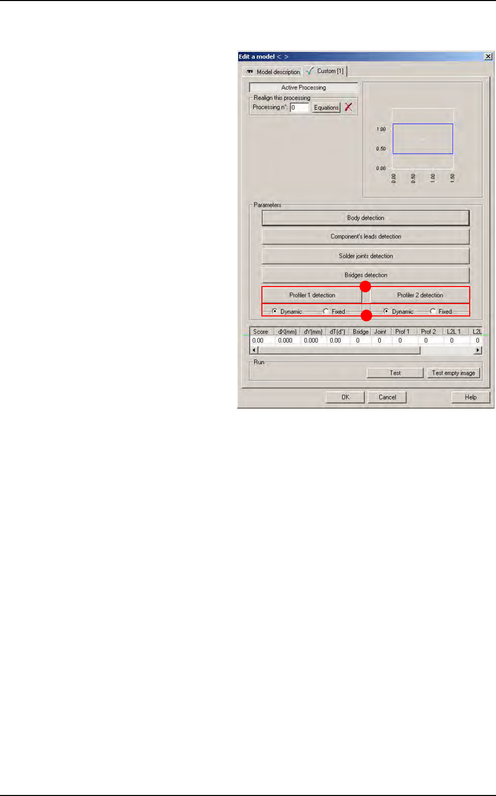
7.9.2 Profiler™ tool using
Choose the treatment operation: a
new
Custom tab appears behind
the
Model description tab. Click on
it, the window below appears.
1. In the Custom tab, click on Profil-
er 1/2 detection
buttons (A) to
program 2 different Profiler™.
This particularity allows to place 2
Profiler
™
on each lead. For exam-
ple, 1 on lead and 1 on joint or 2
on lead.
2. Choose the Profiler™ mode, tick
Dynamic if you want a dynamic
profile or tick
Fixed if you want a
fixed profile (
B).
A
B
Profiler
™
in Custom
Tools library
Vision 2007 4.10 User Manual Rev 01 7 - 47
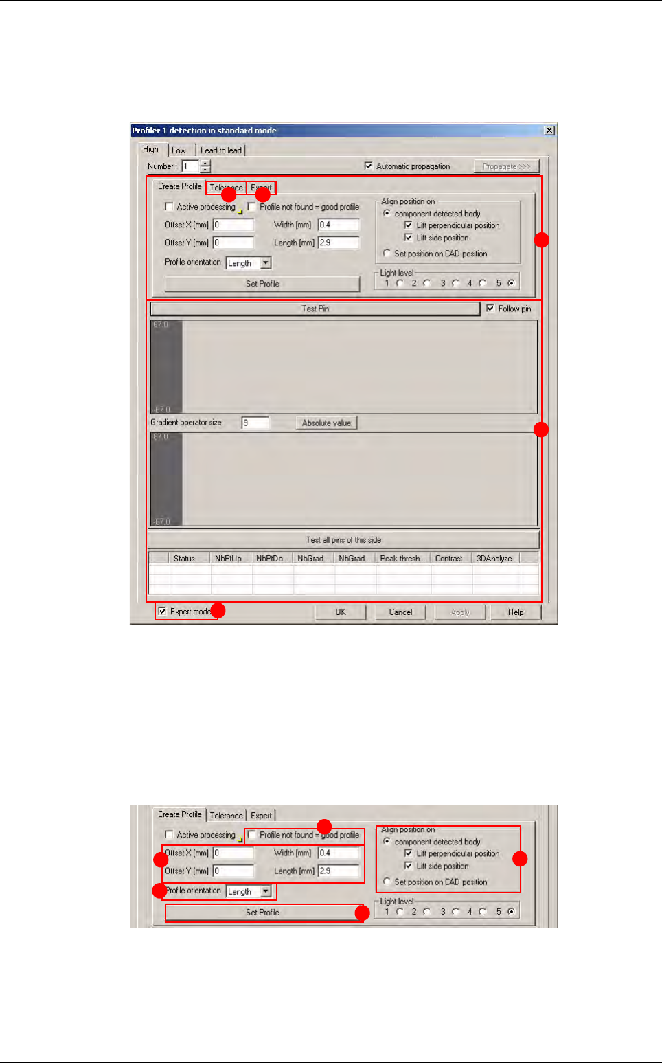
7.9.2.1 Profiler
™
tool window description
Global adjustment tool
Click on Profile 1/2 detection button, the window below appears.
The window is divided in 4 parts:
A Creation
B Global adjustment tool profile and result display (Standard mode):
Gradient operator size: level of gradient smoothing
C Global adjustment tool algorithm (Advanced mode)
D The expert mode is only available with Fixed mode
Creation part
A Definition of the Profiler™ size and position.
B Definition of the orientation of the Profiler™.
C D
B
A
D
A
E
D
B
C
Profiler
™
in Custom