VI User Manual.pdf - 第212页
Tools library 7 - 50 Vision 2007 4.10 User Manual Re v 01 7.9.2.2 Reference profile creation In Create Profile tab, enter the differ ente values of the profile to create. 1. Define the posit ion, the size and the orienta…
Tools library
Vision 2007 4.10 User Manual Rev 01 7 - 49
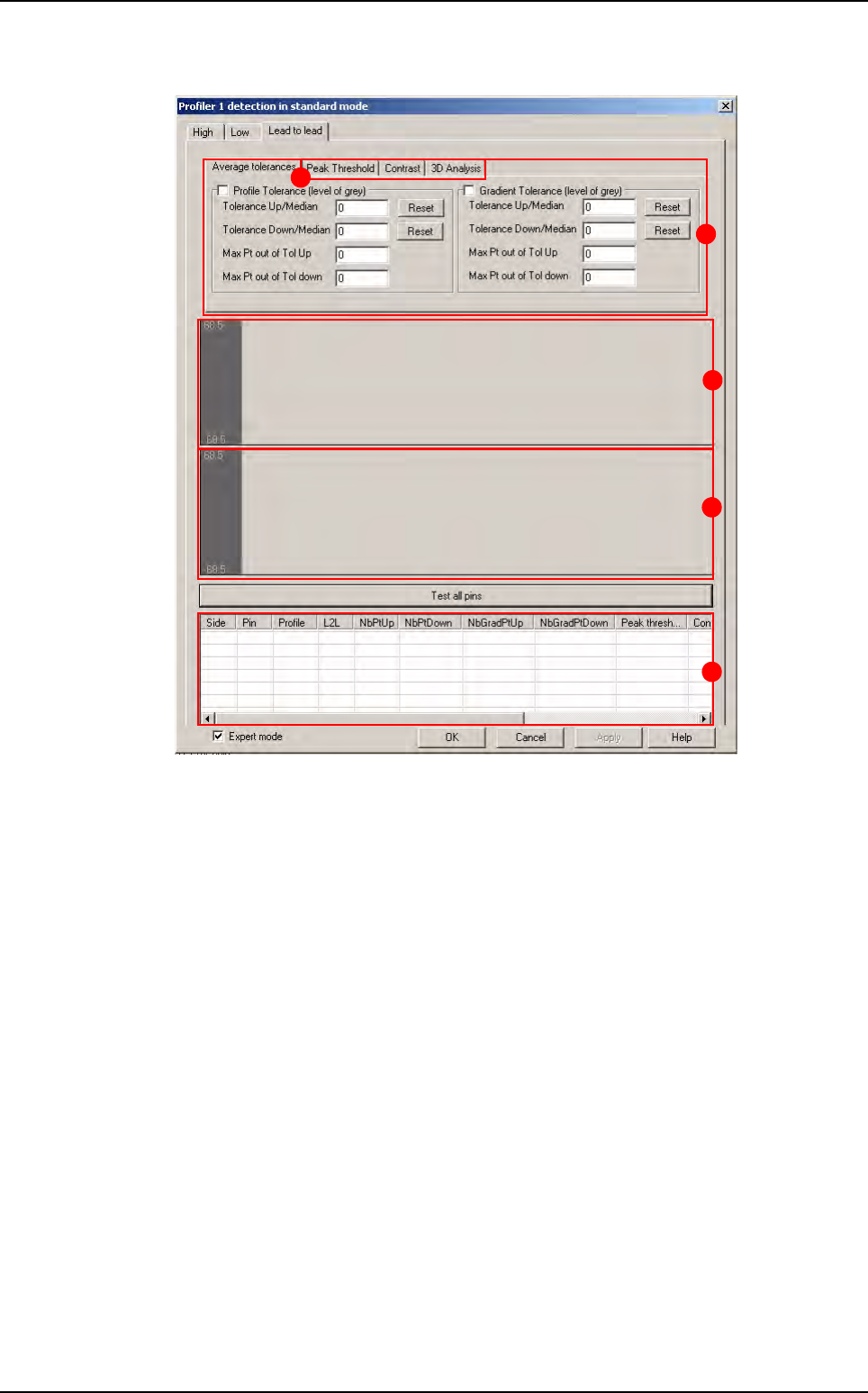
Lead to lead tool
A Lead to lead tolerance setting.
B Area for profiles display.
C Area for gradient display.
D Results chart:
Side: side of component
Pin: number of lead
Profile: status of the lead in the global adjustment tool
L2L: status of the lead in the Lead to lead tool
NbPtUp/Down
: number of point out of tolerances up/down for profile (
Standard mode
)
NbGradientUp/Down: number of point out of tolerances up/down for gradient
(
Standard mode)
Peak threshold: result of peak threshold algorithm (Expert mode)
Contrast: result of contrast algorithm (Expert mode)
3DAnalysis: result of 3D analysis (Expert mode)
Difference: result of the Difference to Average algorithm for the Expert mode al-
gorithm selected (
Peak threshold, Contrast, 3D Analysis) (Expert mode).
E Lead to lead advanced algorithms (only available with fixed mode).
B
A
C
D
E
Profiler
™
in Custom
Tools library
7 - 50 Vision 2007 4.10 User Manual Rev 01
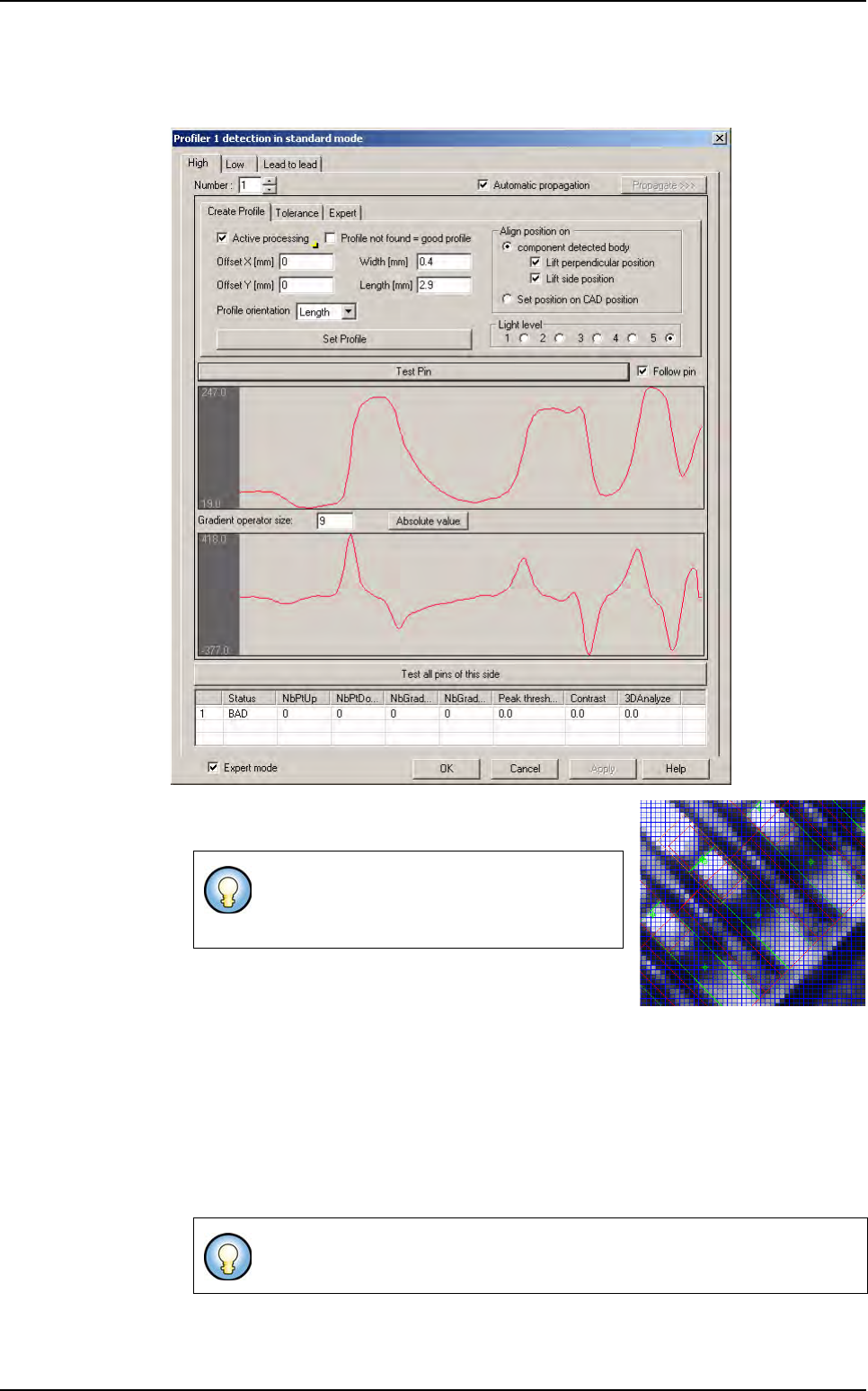
7.9.2.2 Reference profile creation
In Create Profile tab, enter the differente values of the profile to create.
1.
Define the position, the size and the orientation of the Profil-
er™. On the image, the Profiler
™
area appears in orange.
2. Define the light level.
3. In Align position on area, define the realignment op-
tion:
Select
Adjust side position to realign the profile with the side of the lead,
Select
Adjust perpendicular position to realign the profile with the end of lead,
Select
Set position on CAD position to place the profile on the CAD coordinates.
4. Choose a good lead and press the Test pin button to see the profile.
5. Click on Set Profile button to learn the profile reference.
The Profiler
™
can be placed on lead or on
joint, where there is a maximum of difference
between good leads and bad leads.
Profile become blue when you learn it. It became the reference for the Global
tolerance tool.
Profiler
™
in Custom
Tools library
Vision 2007 4.10 User Manual Rev 01 7 - 51
6. Press Propagate >>> button to propagate Profiler
™
characteristics (size, position, ori-
entation and reference profile) to all leads of the sides or component.
7. Click on Test all pin of the side button to see all profiles of the side.
At this stage, Profiler
™
is created. Now, tolerances which include all good lead/joint
(for
Global adjustment and Lead to lead tools) must be determined.
7.9.3 Standard mode
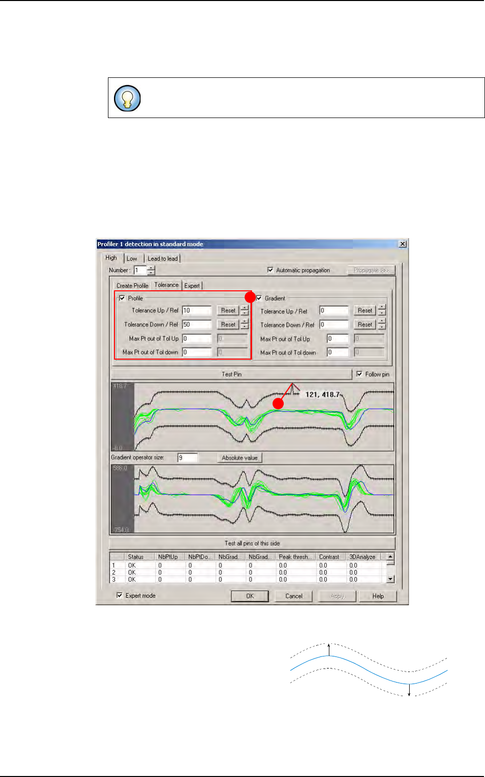
7.9.3.1 Tolerances of global tolerances tool setting
To set the tolerances of global tolerances tool, go in Tolerance tab.
In
Profile area (A), enter a value in Tolerance fields and press Reset button to display
the up/down tolerance lines at wanted value.
This value is in gray level. Tolerances are
constructed in relation to the reference
profile.
Tolerance (B) can be adjusted along the
profile:
1. Click on the point to move, and move it with the mouse.
2. Press Shift button on keyboard to move several points (10) at same time.
3. Use Up/Down arrows to move tolerances and keep manual modifications.
If you click on Test pin button, only the selected lead is displayed.
A
B
Up value
Down value
Reference
Profiler
™
in Custom