VI User Manual.pdf - 第214页
Tools library 7 - 52 Vision 2007 4.10 User Manual Re v 01 4. Click on Reset button to remove all modifications. 7.9.3.2 Lead to lead toleran ces setting To set th e Lead to lead tolerances, go in Lead to lead tab. A Clic…
Tools library
Vision 2007 4.10 User Manual Rev 01 7 - 51
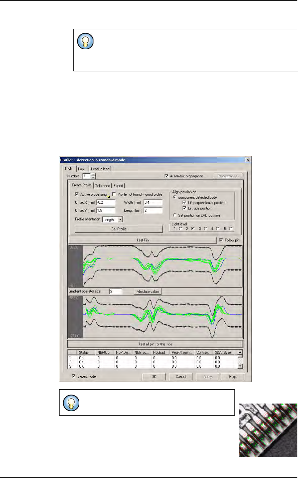
6. Press Propagate >>> button to propagate Profiler
™
characteristics (size, position, ori-
entation and reference profile) to all leads of the sides or component.
7. Click on Test all pin of the side button to see all profiles of the side.
At this stage, Profiler
™
is created. Now, tolerances which include all good lead/joint
(for
Global adjustment and Lead to lead tools) must be determined.
7.9.3 Standard mode
7.9.3.1 Tolerances of global tolerances tool setting
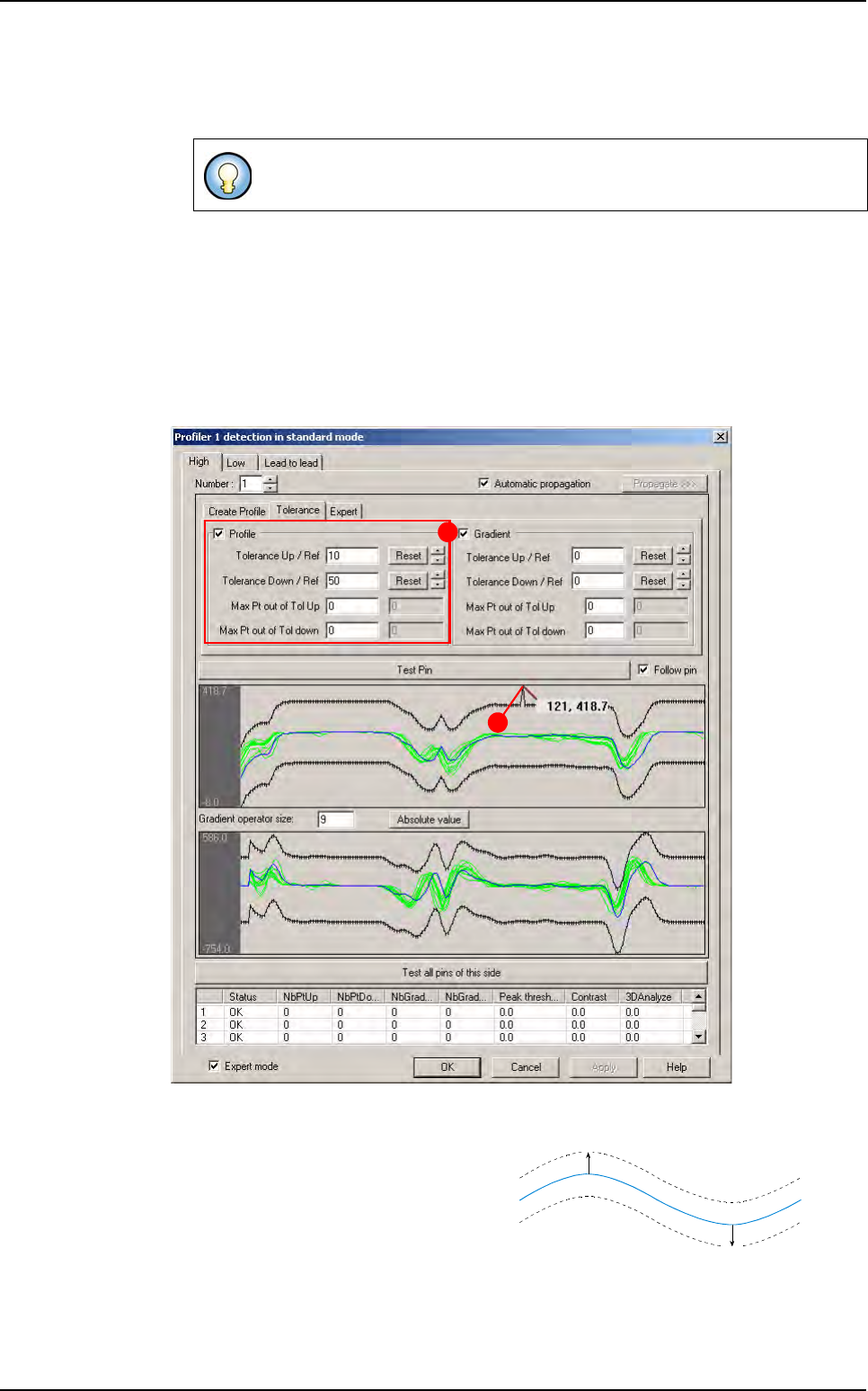
To set the tolerances of global tolerances tool, go in Tolerance tab.
In
Profile area (A), enter a value in Tolerance fields and press Reset button to display
the up/down tolerance lines at wanted value.
This value is in gray level. Tolerances are
constructed in relation to the reference
profile.
Tolerance (B) can be adjusted along the
profile:
1. Click on the point to move, and move it with the mouse.
2. Press Shift button on keyboard to move several points (10) at same time.
3. Use Up/Down arrows to move tolerances and keep manual modifications.
If you click on Test pin button, only the selected lead is displayed.
A
B
Up value
Down value
Reference
Profiler
™
in Custom
Tools library
7 - 52 Vision 2007 4.10 User Manual Rev 01
4. Click on Reset button to remove all modifications.
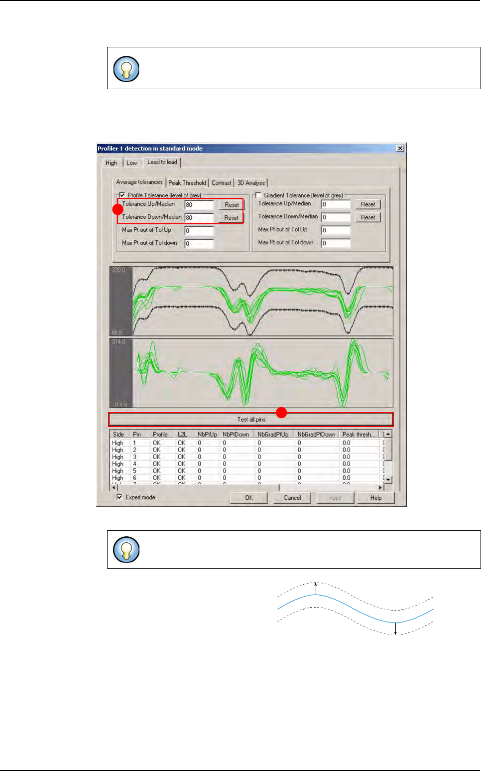
7.9.3.2 Lead to lead tolerances setting
To set the Lead to lead tolerances, go in Lead to lead tab.
A Click on Test all pins button
B
In
tolerance Up/Down/Median
fields
enter the tolerance values and press
Reset
button to display the up/down tol-
erance lines at wanted value. Toler-
ance can be adjusted along the profile:
1. Click on the point to move, and move it with the mouse.
2. Press Shift button on keyboard to move several points (10) at same time.
3. Use Up/Down arrows to move tolerances and keep manual modification.
4. Click on Reset button to remove all modifications.
Tolerance can be applied on the gradient (on Gradient algorithm tab) in the
same way that on the profile.
The
Profiler™ tool test all pins of each side. Tolerances are adapted on the
average of all these profiles.
A
B
Reference
=
Average
of all profiles
Up value
Down value
Profiler
™
in Custom
Tools library
Vision 2007 4.10 User Manual Rev 01 7 - 53
5. Click on Re-test lead to lead button to test all modifications without re-execute each side.
At this stage Profiler™ are programmed in
Standard mode.
7.9.3.3 Tests
Test pin
If you click on Test pin button, the profile of the selected lead is display in green (good
lead) or red (bad lead). The reference curve (in blue) is also display.
Test all pins of the side
If you click Test all pins of this side button, all profiles of the side are display.
Only profiles validates as good by Global tolerances tool are pass to the
Lead to lead tool.
Tolerance can be applied on the gradient (on Gradient algorithm tab) in
the same way that on the
Global adjustment tool.
Global adjustment tool defaults are showed by a blue
segment and blue cross on the image.
Profiler
™
in Custom