VI User Manual.pdf - 第228页
Tools library 7 - 66 Vision 2007 4.10 User Manual Re v 01 7.10.4 Example of use Put Z in the Joint field to return the result of Profiler™ . Profiler ™
Tools library
Vision 2007 4.10 User Manual Rev 01 7 - 65
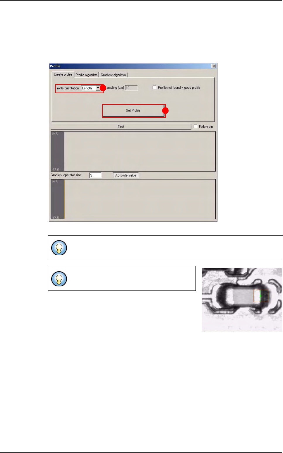
7.10.3 Profiler™ window
In Create profile tab, select the Profile orientation (A):
Length,
Width.
Click on
Set Profile button (B) to learn the profile reference.
Profile become blue when you learn it. It became the reference.
Profile algorithm and Gradient algorithm tabs
are identical to
Profiler™ in Custom version.
A
B
Profiler
™
Tools library
7 - 66 Vision 2007 4.10 User Manual Rev 01
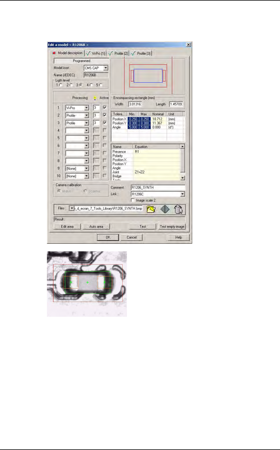
7.10.4 Example of use
Put Z in the Joint field to return the result of Profiler™.
Profiler
™
Tools library
Vision 2007 4.10 User Manual Rev 01 7 - 67
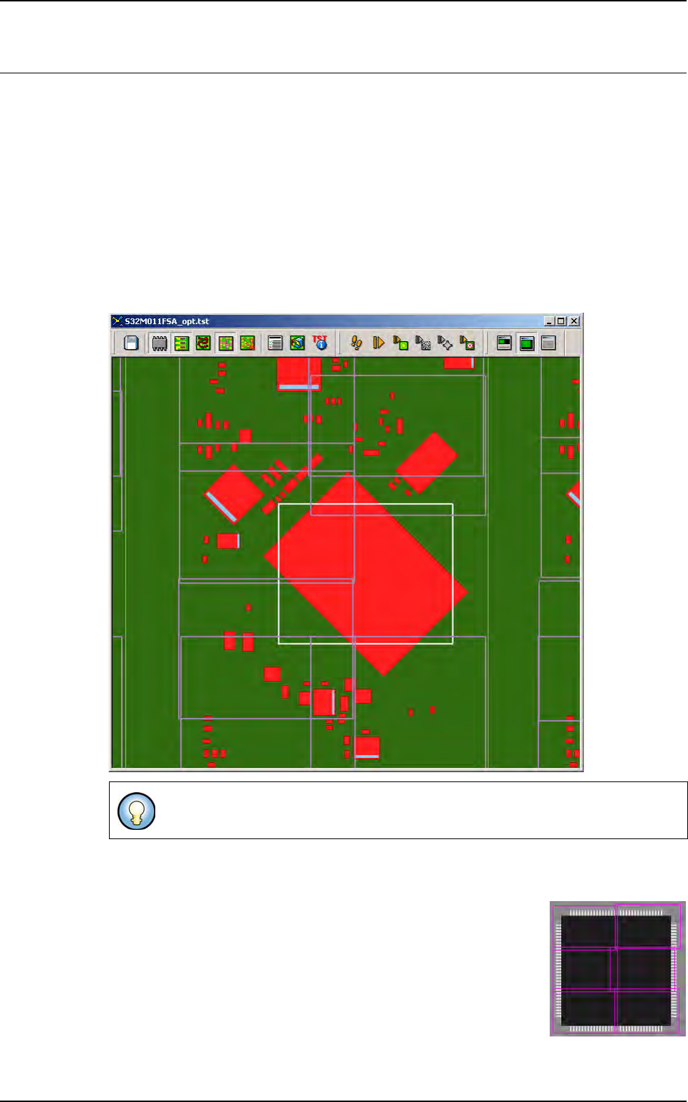
7.11 Multizones
To inspect components larger than the field of view, use the specific model in the library: multizone.
This model allows you to inspect:
Accurate component position,
Solder joints presence on each lead,
Bridges presence between 2 leads,
Component polarity.
7.11.1 In the .tst file
When creating areas, virtual zones are automatically added in white for big components.
The virtual zone is centered on the big component and can not be moved. You can edit the
zone parameters and adjust the light levels used to inspect the big component.
When running multizones component, real zones are created dynam-
ically regarding the treatments programmed in the library. The cam-
era acquisitions use light levels setting as defined in the virtual zone.
The position, the number of real zones and the light levels needed,
are calculated regarding the model programmed in the library. Each
real zone is dedicated to only the component.
When running a multizones component, all the real sub-zones are ac-
quired, even if one treatment has failed (because of multi threads).
Only 1 component is associated to 1 virtual zone.