VI User Manual.pdf - 第231页
Tools library Vision 2007 4.10 User Manua l Rev 01 7 - 69 7.11.1.2 .t st file with no library or no model in the library One parameter in the Default- Value.ini file defines if we make the com- ponent rotate to analyze i…
Tools library
7 - 68 Vision 2007 4.10 User Manual Rev 01
There are 2 cases for multizone affectation:
7.11.1.1 .tst file linked to a library with model programmed in the library
We first consider the model defined in the library
If the model in the library is a mono-zone, then the component in the .tst file will
be a mono-zone.
A test will be performed to check that the component fit in a zone. If some com-
ponents do not fit in a zone, a warning message is displayed and these compo-
nents are affected inside virtual zones. They are considered as multizones
components in the .tst file, and the user will have to create multizones models in
the library.
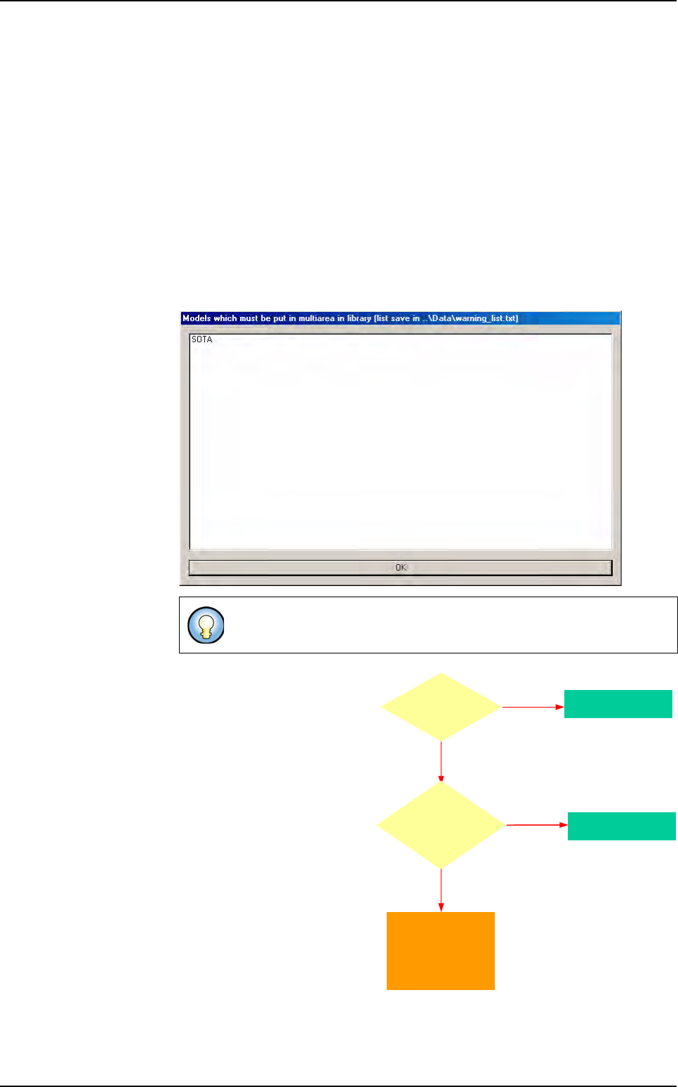
A message box with the list of the models that must be created as mutlizones, is
displayed.
If the model in the library is a
multizones, then the compo-
nent in the .tst file will be a
multizones.
If one topo is too big, then the whole family will be multizones.
Model in
library is a
Multi zone ?
Component becomes
a Multi zones
YES
NO
it is a Mono zone
Component fits
in a zone at
the CAD
angle ?
YES
NO
at least
one topo is too big
Component becomes
a Mono zones
Display a warning
message and the
component is affected to
a virtual zone.
(the user has to create
a Multi zones model
in the library)
Multizones
Tools library
Vision 2007 4.10 User Manual Rev 01 7 - 69
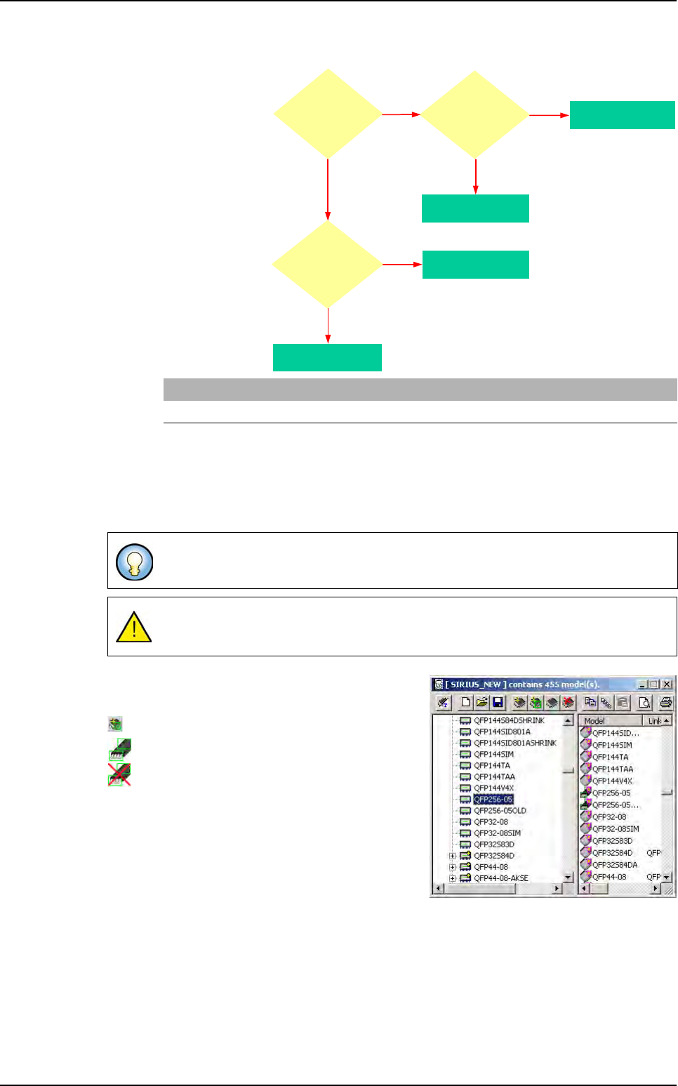
7.11.1.2 .tst file with no library or no model in the library
One parameter
in the
Default-
Value.ini
file
defines if we
make the com-
ponent rotate to
analyze it as a
multizones or
not.
7.11.2 In the library
There is a special menu item to create a multizones model. You must have a synthetic image
of your component to create a multizones model. This image is used to program all the treat-
ments for polarity, joints, bridges, ... So it must contain all the information you need.
You can link multizones together, but not normal
models with multi zones.
Icon to create a multizones model.
Icon of the model programmed.
Icon of the model not programmed.
[MultiZone]
Rotate component to consider as MZ (0,1) =0
To draw polarity mark on type 2 synthetic image, open the picture with
ImgEdit
software.
Be careful not to draw on the bottom part of the picture, because it contains the
BuildModel information.
NO
at least
one topo is too big
NO
YES
Component
fits in a zone
at any angle ?
YES
Component becomes
a Multi zones
Component
fits in a zone
at the CAD
angle ?
YES
Component becomes
a Mono zones
Component becomes
a Multi zones
NO
at least
one topo is too big
Component becomes
a Mono zones
Parameter:
Rotate component
to consider as
MZ = 1 (ini file)
Multizones
Tools library
7 - 70 Vision 2007 4.10 User Manual Rev 01
7.11.3 Multizones model programming
Draw a synthetic image with BuildModel. Check the BuildModel pixel
size configuration and make it match your vision calibration.
In the library window click on this icon in the tool bar. Then appears a
box where you specify the name of the component.
To create a multizones model, after you draw a synthetic image with BuildModel, in the
Mod-
els
menu go to New multi area model… sub menu, then appears the box where you specify
the name of the component.
Later select the synthetic image created with build (.bmp file) in the
Open a BuildModel file
window.
7.11.4 Model description
A lot of parameters can not be changed. They are automatically set when reading the Build-
Model image information:
You can not change the model icon.
Select tools among the list.
You can not edit the encompassing rectangle.
Enter the inspection tolerances for the current model.
You can not change the model image of the display camera associated to the model.
7.11.5 Vi-Pro, Edge, Histogram tools for multizones model
Program these tools exactly the same way you do for normal
model.
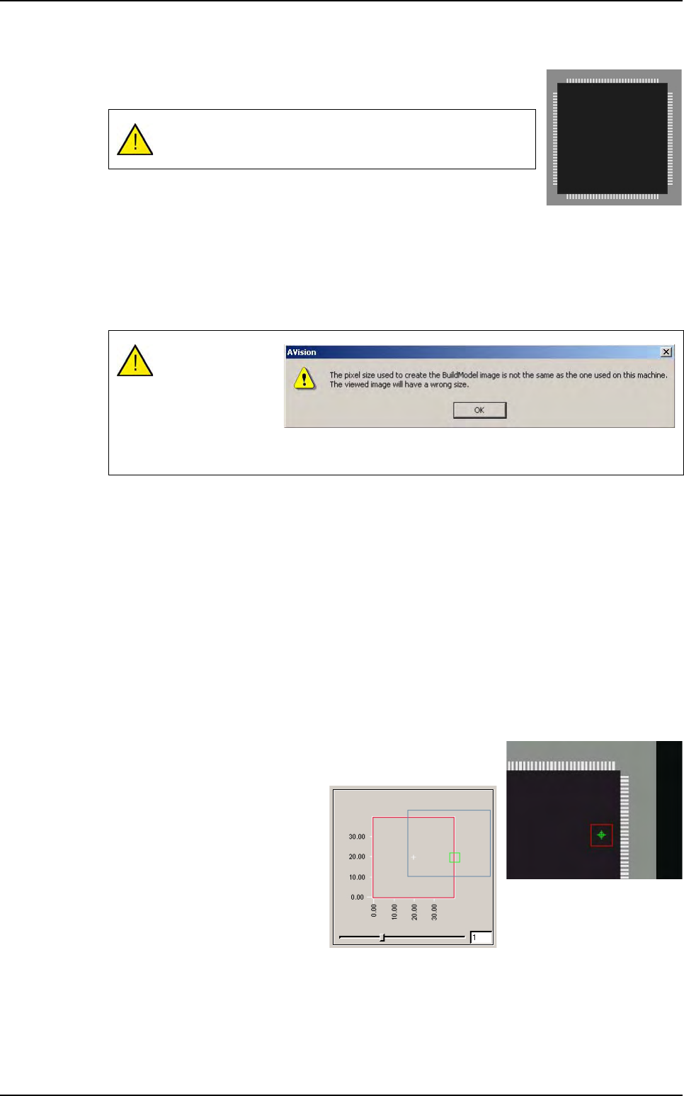
To place the treatments areas on
the right part of the component,
use the slider to see all the sub
zones created.
The multizones model can be only created with BuildModel
Type 2.
Comparison of the
image pixels size
and the machine
calibration.
This message is
just to aware you of
any possible difference.
Multizones