VI User Manual.pdf - 第233页
Tools library Vision 2007 4.10 User Manua l Rev 01 7 - 71 7.1 1.6 Custom tool for multizones model The custom too l requires specific su b zones which are only us ed for this inspectio n. When selecting the custom to ol,…
Tools library
7 - 70 Vision 2007 4.10 User Manual Rev 01
7.11.3 Multizones model programming
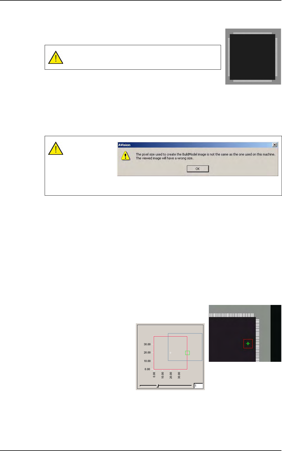
Draw a synthetic image with BuildModel. Check the BuildModel pixel
size configuration and make it match your vision calibration.
In the library window click on this icon in the tool bar. Then appears a
box where you specify the name of the component.
To create a multizones model, after you draw a synthetic image with BuildModel, in the
Mod-
els
menu go to New multi area model… sub menu, then appears the box where you specify
the name of the component.
Later select the synthetic image created with build (.bmp file) in the
Open a BuildModel file
window.
7.11.4 Model description
A lot of parameters can not be changed. They are automatically set when reading the Build-
Model image information:
You can not change the model icon.
Select tools among the list.
You can not edit the encompassing rectangle.
Enter the inspection tolerances for the current model.
You can not change the model image of the display camera associated to the model.
7.11.5 Vi-Pro, Edge, Histogram tools for multizones model
Program these tools exactly the same way you do for normal
model.
To place the treatments areas on
the right part of the component,
use the slider to see all the sub
zones created.
The multizones model can be only created with BuildModel
Type 2.
Comparison of the
image pixels size
and the machine
calibration.
This message is
just to aware you of
any possible difference.
Multizones
Tools library
Vision 2007 4.10 User Manual Rev 01 7 - 71
7.11.6 Custom tool for multizones model
The custom tool requires specific sub zones which are only used for this inspection. When
selecting the custom tool, the sub zones are automatically computed. In the custom tool for
multizones:
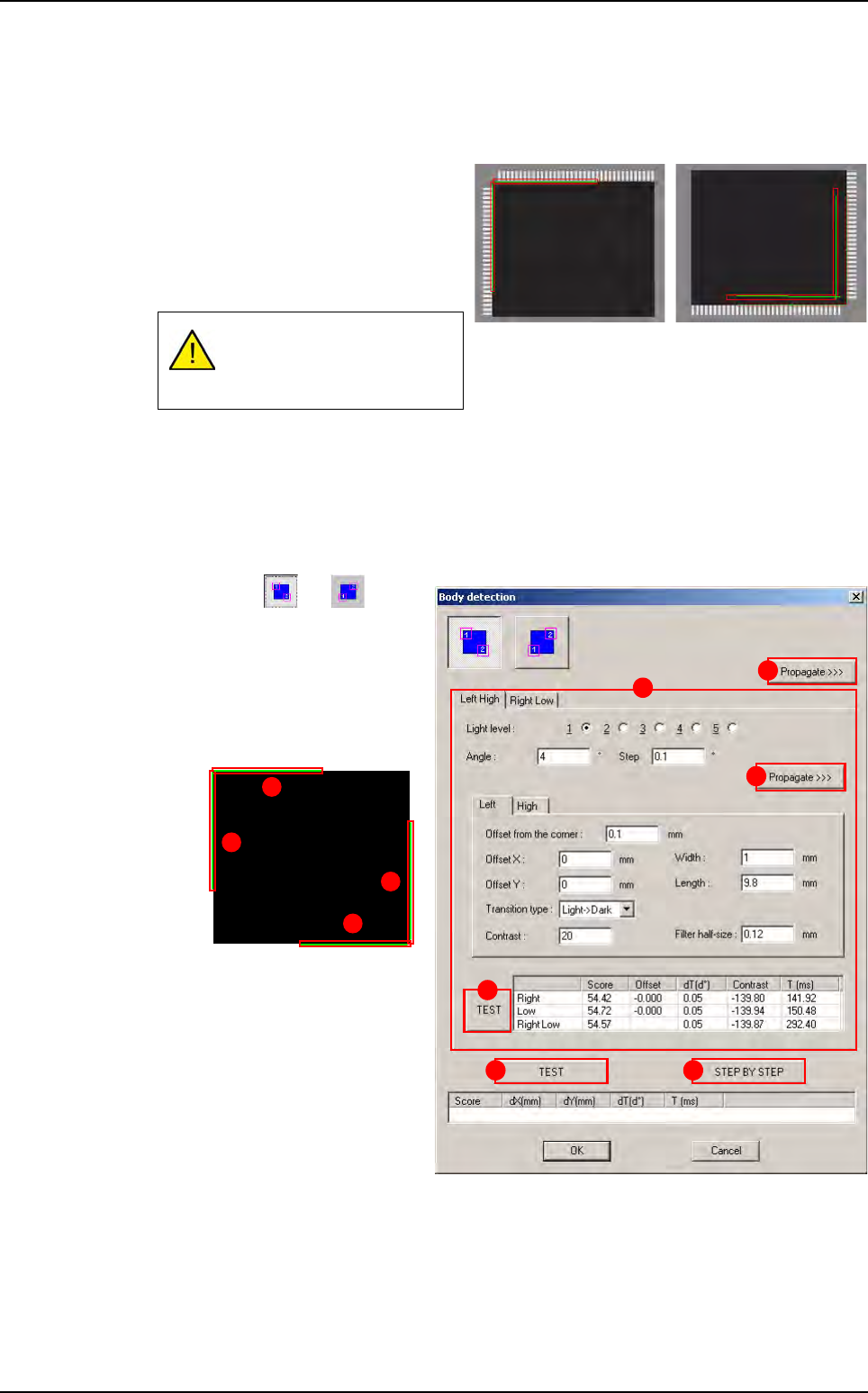
The body detection is done on 2 opposite
corners with 2 perpendicular helicopter
edges.
The component position and presence
is only computed with the body detec-
tion and not leads detection.
Only joints tools are realigned with the leads position. The bridges tools are realigned with
the body position.
7.11.7 Custom tool edition
7.11.7.1 Body detection
Press or button
to select the corners to use
for body detection.
In
Left Hight and Right
Low
(A) tabs the parame-
ters of the 4 rotating edges
are displayed.
Press
Propagate >>> (B)
button to propagate the pa-
rameters to the opposite
corner (Left/High sides on
this example).
Press
Propagate >>> (C)
button (in the tab) to propa-
gate the parameters to the
second edge of the same
corner (Right side on this
example).
Press
TEST (D) button (in the tab) to test the 2 rotating edges of the current corner.
Press
TEST (E) button to test the 4 rotating edges of the 2 corners.
Press
STEP BY STEP (F) button to test the 4 rotating edges of the 2 corners step
by step.
If no lead is detected on one
side, it does not return miss-
ing component.
A
B
C
D
E F
3
4
1
2
Multizones
Tools library
7 - 72 Vision 2007 4.10 User Manual Rev 01
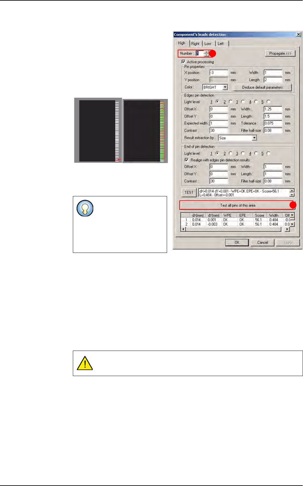
7.11.7.2 Component’s leads detection
When you increase the lead num-
ber (
A), the corresponding sub
zone is automatically displayed on
the camera display.
Press
Test all pins of this area
(B) button to test all the leads of
the sub zone displayed.
Result of the one lead test Result of all area’s
leads
7.11.8 Custom tool execution
7.11.8.1 Execution of one reference
Ctrl + E is the only way to debug your model on a real picture,
It takes pictures of each sub zones with the 5 light levels to ensure the changes,
It runs all the links and takes the number of pictures required.
7.11.8.2 Global execution
All the required pictures are taken for each link.
Some of the leads dis-
played on this picture
may be tested on the
following sub zone. That
is why you can not see
their test results.
Multizones are very time consuming.
A
B
Multizones